
Instruction Manual

CS2200-OTP
12 DS842F2
Selection of the user defined ratio from the four stored ratios is made by using the M[1:0] pins.
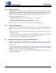
5.3.4 Ratio Configuration Summary
The R
UD
is the user defined ratio for which up to four different values (Ratio
0-3
) can be stored in the one
time programmable memory. The M[1:0] pins then select the user defined ratio to be used as well as the
modal configuration set. R-Mod is applied accordingly. The user defined ratio and ratio modifier make up
the effective ratio R
EFF
, the final calculation used to determine the output to input clock ratio. The effective
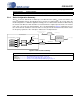
ratio is then corrected for the internal dividers. The conceptual diagram in Figure 6 summarizes the fea-
tures involved in the calculation of the ratio values used to generate the fractional-N value which controls
the Frequency Synthesizer. The subscript ‘4’ indicates the modal parameters.
Figure 6. Ratio Feature Summary
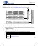
Referenced Control Parameter Definition
M[1:0] pins.............................“M1 and M0 Mode Pin Functionality” on page 14
Referenced Control Parameter Definition
Ratio 0-3................................“Ratio 0 - 3” on page 18
M[1:0] pins.............................“M1 and M0 Mode Pin Functionality” on page 14
RModSel[1:0] ........................“R-Mod Selection (RModSel[1:0])” section on page 17
RefClkDiv[1:0] .......................“Reference Clock Input Divider (RefClkDiv[1:0])” on page 18
Effective Ratio R
EFF
Ratio Format
SysClk
PLL Output
Frequency
Synthesizer
Ratio 0
Ratio 1
Ratio 2
Ratio 3
12.20
M[1:0] pins
RModSel[1:0]
4
Ratio
Modifier
R Correction
RefClkDiv[1:0]
Timing Reference Clock
(XTI/REF_CLK)
Divide
RefClkDiv[1:0]
Static Ratio, ‘N’
User Defined Ratio R
UD
M2 pin