
Instruction Manual


CS2200-OTP
10 DS842F2
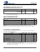
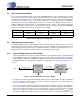
example of how to determine the range of RefClk frequencies around 12 MHz to be used in order to
achieve the lowest jitter PLL output at a frequency of 12.288 MHz is as follows:
where:
and
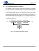
5.2.2 Crystal Connections (XTI and XTO)
An external crystal may be used to generate RefClk. To accomplish this, a 20 pF fundamental mode par-
allel resonant crystal must be connected between the XTI and XTO pins as shown in Figure 5. As shown,
nothing other than the crystal and its load capacitors should be connected to XTI and XTO. Please refer
to the “AC Electrical Characteristics” on page 7 for the allowed crystal frequency range.
5.2.3 External Reference Clock (REF_CLK)
For operation with an externally generated REF_CLK signal, XTI/REF_CLK should be connected to the
reference clock source and XTO should be left unconnected or terminated through a 47 kΩ resistor to
GND.
Referenced Control Parameter Definition
RefClkDiv[1:0] .......................“Reference Clock Input Divider (RefClkDiv[1:0])” on page 18
-80 -60 -40 -20 0 20 40 60 80
20
40
60
80
100
120
140
160
180
Normalized REF__CLK Frequency (kHz)
Typical Base Band Jitter (psec)
CLK__OUT Jitter
-15 kHz +15 kHz
CLK__OUT
f
*32/N
Figure 4. REF_CLK Frequency vs. a Fixed CLK_OUT
f
L
f
RefClk
f
H
≤≤
f
L
f
CLK_OUT
31
32
------
15kHz+×=
12.288MHz 0.96875 15kHz+×=
11.919MHz=
f
H
f
CLK_OUT
32
32
------
15kHz–×=
12.288MHz 115kHz+×=
12.273MHz=
XTI XTO
40 pF 40 pF
Figure 5. External Component Requirements for Crystal Circuit