
Instruction Manual

CS2200-CP
14 DS759F2
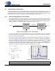
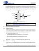
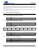
5.2.4 Ratio Configuration Summary
The R
UD
is the user defined ratio stored in the register space. R-Mod is applied if selected. The user de-
fined ratio, and ratio modifier make up the effective ratio R
EFF
, the final calculation used to determine the
output to input clock ratio. The effective ratio is then corrected for the internal dividers. The conceptual
diagram in Figure 8 summarizes the features involved in the calculation of the ratio values used to gen-
erate the fractional-N value which controls the Frequency Synthesizer.
Figure 8. Ratio Feature Summary
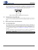
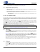
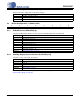
5.3 PLL Clock Output
The PLL clock output pin (CLK_OUT) provides a buffered version of the output of the frequency synthesizer.
The driver can be set to high-impedance with the ClkOutDis bit.
The output from the PLL automatically drives a static low condition while the PLL is un-locked (when the
clock may be unreliable). This feature can be disabled by setting the ClkOutUnl bit, however the state
CLK_OUT may then be unreliable during an unlock condition.
Figure 9. PLL Clock Output Options
Referenced Control Register Location
Ratio......................................“Ratio (Address 06h - 09h)” on page 21
RModSel[2:0] ........................“R-Mod Selection (RModSel[2:0])” section on page 20
RefClkDiv[1:0] .......................“Reference Clock Input Divider (RefClkDiv[1:0])” on page 22
Referenced Control Register Location
ClkOutUnl..............................“Enable PLL Clock Output on Unlock (ClkOutUnl)” on page 22
ClkOutDis..............................“PLL Clock Output Disable (ClkOutDis)” on page 20
Effective Ratio R
EFF
Ratio Format
SysClk
PLL Outpu
Frequency
Synthesizer
R Correction
N
Ratio 12.20
Ratio
Modifier
RModSel[2:0]
RefClkDiv[1:0]
Timing Reference Clock
(XTI/REF_CLK)
Divide
RefClkDiv[1:0]
User Defined Ratio R
UD
PLL Locked/Unlocked
PLL Output
2:1 Mux
ClkOutDis
2:1 Mux
ClkOutUnl
0
PLL Clock Output Pin
(CLK_OUT)
0
1
0
1
PLL Clock Output
PLLClkOut