
User guide

CS2100-OTP
22 DS841F2
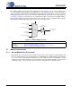
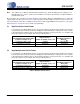
6.3.3 Enable PLL Clock Output on Unlock (ClkOutUnl)
Defines the state of the PLL output during the PLL unlock condition.
6.3.4 Low-Frequency Ratio Configuration (LFRatioCfg)
Determines how to interpret the currently indexed 32-bit User Defined Ratio.
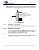
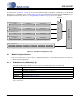
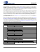
6.3.5 M2 Pin Configuration (M2Config[2:0])
Controls which special function is mapped to the M2 pin.
6.3.6 Clock Input Bandwidth (ClkIn_BW[2:0])
Sets the minimum loop bandwidth when locked to CLK_IN.
ClkOutUnl Clock Output Enable Status
0 Clock outputs are driven ‘low’ when PLL is unlocked.
1 Clock outputs are always enabled (results in unpredictable output when PLL is unlocked).
Application: “PLL Clock Output” on page 16
LFRatioCfg Ratio Bit Encoding Interpretation
0 20.12 - High Multiplier.
1 12.20 - High Accuracy.
Application: “User Defined Ratio (RUD)” on page 14
M2Config[2:0] M2 pin function
000 Disable CLK_OUT pin.
001 Disable AUX_OUT pin.
010 Disable CLK_OUT and AUX_OUT.
011 RModSel[1:0] Modal Parameter Enable.
100 Reserved.
101 Reserved.
110 Reserved.
111 Force AuxOutSrc[1:0] = 10 (PLL Clock Out).
Application: “M2 Mode Pin Functionality” on page 18
ClkIn_BW[2:0] Minimum Loop Bandwidth
000 1 Hz
001 2 Hz
010 4 Hz
011 8 Hz
100 16 Hz
101 32 Hz
110 64 Hz
111 128 Hz
Application: “Adjusting the Minimum Loop Bandwidth for CLK_IN” on page 13