
User guide

CS2100-OTP
DS841F2 21
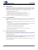
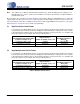
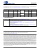
6.1.2 Auxiliary Output Source Selection (AuxOutSrc[1:0])
Selects the source of the AUX_OUT signal.
Note: When set to 11, the AuxLockCfg global parameter sets the polarity and driver type (“AUX PLL
Lock Output Configuration (AuxLockCfg)” on page 21).
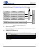
6.2 Ratio 0 - 3
The four 32-bit User Defined Ratios are stored in the CS2100’s one time programmable memory. See “Out-
put to Input Frequency Ratio Configuration” on page 14 and “Calculating the User Defined Ratio” on
page 23 for more details.
6.3 Global Configuration Parameters
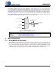
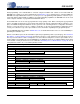
6.3.1 AUX PLL Lock Output Configuration (AuxLockCfg)
When the AUX_OUT pin is configured as a lock indicator (AuxOutSrc[1:0] modal parameter = ‘11’), this
global parameter configures the AUX_OUT driver to either push-pull or open drain. It also determines the
polarity of the lock signal. If AUX_OUT is configured as a clock output, the state of this parameter is dis-
regarded.
Note: AUX_OUT is an unlock indicator, signalling an error condition when the PLL is unlocked. There-
fore, the pin polarity is defined relative to the unlock condition.
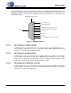
6.3.2 Reference Clock Input Divider (RefClkDiv[1:0])
Selects the input divider for the timing reference clock.
AuxOutSrc[1:0] Auxiliary Output Source
00 RefClk.
01 CLK_IN.
10 CLK_OUT.
11 PLL Lock Status Indicator.
Application: “Auxiliary Output” on page 17
AuxLockCfg AUX_OUT Driver Configuration
0 Push-Pull, Active High (output ‘high’ for unlocked condition, ‘low’ for locked condition).
1 Open Drain, Active Low (output ‘low’ for unlocked condition, high-Z for locked condition).
Application: “Auxiliary Output” on page 17
RefClkDiv[1:0] Reference Clock Input Divider REF_CLK Frequency Range
00 ÷ 4. 32 MHz to 75 MHz (50 MHz with XTI)
01 ÷ 2. 16 MHz to 37.5 MHz
10 ÷ 1. 8 MHz to 18.75 MHz
11 Reserved.
Application: “Internal Timing Reference Clock Divider” on page 11