
User guide

CS1680
8 DS1055F1
5. GENERAL DESCRIPTION
5.1 Overview
The CS1680 is a cascade boost-buck dimmable LED
driver for the 12V halogen lamp-replacement market.
The CS1680 uses a Cirrus Logic proprietary intelligent
digital control that provides exceptional single-lamp and
multi-lamp transformer compatibility for non-dimmer
systems and dimmer systems paired with electronic and
magnetic low-voltage transformers.
The CS1680 integrates a continuous conduction mode
(CCM) boost converter that provides transformer
compatibility and dimmer compatibility. An adaptive
digital algorithm controls the boost stage and dimmer
compatibility operation mode to enable flicker-free
operation down to 5% output current with leading-edge
and trailing-edge dimmers.
5.2 IC Startup and Power Supply
The startup circuit is constructed of a linear regulator
and charge pump, and is used to supply a power-on
voltage to the CS1680. The device provides a GPIO pin
that is used to disable the startup circuit once the boost
output voltage reaches 50% of full scale.
The linear regulator circuit uses transistor Q1 to provide
a supply voltage to a Schmitt-trigger inverter which
enables the charge pump circuit. The GPIO pin is
tri-stated while the controller is held in reset due to low
supply voltage. The charge pump increases the voltage
until the device starts converting. Once the supply
voltage V
DD
exceeds threshold voltage V
ST(th)
, the
controller polls the boost output voltage for 50% of full
scale before driving the GPIO pin low to disable the
startup circuit.
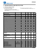
5.3 Boost Stage
The boost stage in the CS1680 is a low-side
asynchronous boost converter. Once the IC reaches its
UVLO start threshold voltage V
ST(th)
and begins
operating, the CS1680 executes a detection algorithm
to set the operating state of the IC (see Table 1 on
page 8). The boost stage utilizes a continuous current
mode (CCM) control algorithm.
5.3.1 Dimmer Compatibility
The CS1680 dimmer switch detection algorithm
determines if the solid-state lighting (SSL) system is
controlled: first, using a regular switch or a leading-edge
dimmer paired with a magnetic transformer, or a
12VAC/VDC source (Mode1); second, by a regular
switch or a trailing-edge dimmer paired with an electronic
transformer (Mode2); third, by a leading-edge dimmer
paired with an electronic transformer (Mode3).
Dimmer switch detection is implemented using a
process of elimination. The method of elimination
progresses through the detection algorithm to find the
best matching state of operation. In an attempt to find a
dimmer compatible mode, the detection algorithm starts
in Mode1, then tries Mode2, if Mode1 and Mode2 are
excluded the algorithm defaults to Mode3.
Mode1
In Mode1, the detectable inputs are a leading-edge
dimmer paired with a magnetic transformer, no dimmer
switch paired with a magnetic transformer, or a
12VDC/VAC source. Upon detection of a magnetic
transformer, the CS1680 operates in a PFC conduction
mode where the device provides a power factor that is
in excess of 0.9. The boost peak current I
BSTPK
is
modulated across the input voltage to follow a constant
resistance. The target resistance is modulated to
provide boost output regulation. The RMS input voltage
is used to determine the output LED current as a
fraction of full scale. If a DC input voltage is detected,
the controller will set the LED output at 100% of the
available RMS energy.
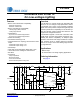
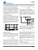
The boost output voltage V
BST
is measured at the
trough of the rectified voltage every half-line cycle and
compared against the regulation point, which is set by
resistor R
BST
(see Figure 11 on page 10). The voltage
difference, the setting of LED output current I
OUT
, and
the clamp activity are used in the control loop to scale
the boost inductor current allowing the boost output
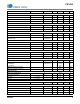
Boost
Mode
Source Line Switch Digital Control Loop
Mode1
12 VAC/VDC Non-dimming
Executes a boost peak-
current algorithm with
PFC based control.
Magnetic
Transformer
Leading-edge
Dimmer
Non-dimming
Mode2
Electronic
Transformer
Trailing-edge
Dimmer
Executes a constant
boost peak-current
algorithm during the turn-
on time of the electronic
transformer.
Non-dimming
Mode3
Electronic
Transformer
Leading-edge
Dimmer
Executes a constant
power control algorithm
where the boost inductor
current is controlled by
the instantaneous
rectified voltage signal.
Table 1. Operating State