
User guide

CS1680
DS1055F1 3
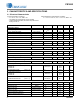
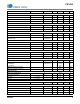
2. PIN DESCRIPTION
Pin Name
Pin # I/O
Description
CTRL2
1IN
Peak Current — Connect a resistor to this pin to set the comparator threshold to
reflect the desired boost peak current in Trailing Edge Electronic Trans-
former Mode (Mode 2).
eOTP
2IN
External Overtemperature Protection — Connect an external NTC thermistor to
this pin, allowing the internal A/D converter to sample the change to NTC resistance.
BSTSENSE
3IN
Boost Stage Current Sense — The current flowing in the boost stage FET is
sensed across a resistor. The resulting voltage is applied to this pin and digitized for
use by the boost stage computational logic to determine the FET duty cycle.
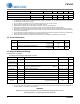
GND
4PWR
Ground — Common reference. Current return for both the input signal portion of the
IC and the gate driver.
BSTGD
5OUT
Boost Gate Driver — Gate drive for the boost stage power FET.
VDD
6PWR
IC Supply Voltage —
Connect a storage capacitor to this pin to serve as a reservoir for
operating current for the device, including the gate drive current to the power transistor
.
GPIO
7IN/OUT
General Purpose Input/Output — Used to drive the FET gate for the startup circuit.
NC
8IN
No Connect — Leave pin not connected.
BUCKZCD
9IN
Buck Stage Zero-current Detect — Buck stage inductor sensing input. The pin is
connected to the drain of the buck stage power FET with a capacitor.
NC
10 IN
No Connect — Leave pin not connected.
CLAMP
11 OUT
Voltage Clamp Current Source — Connect to a voltage clamp circuit on the output
of the boost stage.
BUCKGD
12 OUT
Buck Gate Driver — Gate drive for the buck stage power FET.
BUCKSENSE
13 IN
Buck Stage Current Sense — The current flowing in the buck stage FET is sensed
across a resistor. The resulting voltage is applied to this pin and digitized for use by
the buck stage computational logic to determine the FET duty cycle.
VAC
14 IN
Rectifier Voltage Sense — A current proportional to the rectified line voltage is fed
into this pin. The current is measured with an A/D converter.
BSTOUT
15 IN
Boost Output Voltage Sense — A current proportional to the boost output is fed
into this pin. The current is measured with an A/D converter.
CTRL1
16 IN
Boost Stage Constant — Connect a resistor to this pin to set the constant ratio for
the boost stage current calculations in Leading Edge Electronic Transformer Mode
(Mode 3).
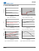
General Purpose Input/Output
Boost Gate Driver
Ground
Peak Current
E
xternal Overtemperature Protection
No Connect
GPIO
VDDIC Supply Voltage
BSTGD
GND
CTRL2
NC
CLAMP
BUCKGD
BUCKSENSE
VAC
BSTOUT
CTRL1
eOTP
BSTSENSEBoost Stage Current Sense
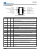
16-lead TSSOP
NC
BUCKZCD
7
6
5
4
3
2
1
10
11
12
13
14
15
16
8
9
No Connect
Voltage Clamp Current Source
Buck Gate Driver
Buck Stage Current Sense
Rectifier Voltage Sense
Boost Output Voltage Sense
Boost Stage Constant
Buck Stage Zero-current Detect
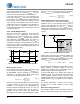
Figure 2. CS1680 Pin Assignments