
User Manual


CS1501
DS927F4 5
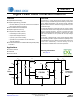
Notes: 1. External circuitry should be designed to ensure the ZCD sink current pulled from the internal clamp diode when it
is forward biased does not exceed specification.
2. Specifications guaranteed by design and are characterized and correlated using statistical process methods.
3. STBY
is designed to be driven by an open collector. The input is internally pulled up with a 600k resistor.
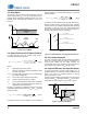
4. For test purposes, load capacitance (C
L
) is 1nF and is connected as shown in the following diagram.
Brownout Protection (BP)
Input Brownout Protection Threshold Gate Drive Turns Off I
BP(lower)
-31.6-A
Input Brownout Recovery Threshold Gate Drive Turns On I
BP(upper)
-39.6-A
Thermal Protection
2
Thermal Shutdown Threshold T
SD
134 147 159 °C
Thermal Shutdown Hysteresis T
SD(Hy)
-9-°C
STBY Input
3
Logic Threshold Low - - 0.8 V
Logic Threshold High V
DD
-0.8 - - V
Parameter Condition Symbol Min Typ Max Unit
GD OUT
GD
GND
CS
VDD
Buffer
S
1
R
1
R
2
R
3
TP
C
L
1nF
+15V
-15V
S
2
V
DD