
User Manual
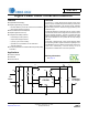
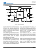
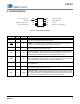


CS1501
4 DS927F4
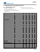
3. CHARACTERISTICS AND SPECIFICATIONS
3.1 Electrical Characteristics
Typical characteristics conditions:
T
A
=25°C, V
DD
= 13V, GND = 0V
All voltages are measured with respect to GND.
Unless otherwise specified, all currents are positive when
flowing into the IC.
Minimum/Maximum characteristics conditions:
T
J
= -40° to +125°C, V
DD
= 10V to 15V, GND = 0V
Parameter Condition Symbol Min Typ Max Unit
V
DD
Supply Voltage
Operating Range After Turn-on V
DD
7.9 - 17.0 V
Turn-on Threshold Voltage V
DD
Increasing V
DD(on)
9.8 10.2 10.5 V
Turn-off Threshold Voltage (UVLO) V
DD
Decreasing V
DD(off)
7.9 8.1 8.3 V
UVLO Hysteresis V
Hys
-2.1-V
Zener Voltage I
DD
=20mA V
Z
17.0 17.9 19.0 V
V
DD
Supply Current
Startup Supply Current V
DD
=V
DD(on)
I
ST
-6895A
Operating Supply Current
4
C
L
= 1nF, fsw = 70kHz I
DD
-1.52.1mA
Standby Supply Current STBY
< 0.8V I
SB
-80125A
Reference
Reference Current I
ref
- 129 - A
PFC Gate Drive
Output Source Resistance I
GD
= 100mA, V
DD
=13V R
OH
-9-
Output Sink Resistance I
GD
= -200mA, V
DD
=13V R
OL
-6-
Rise Time
4
C
L
=1nF,V
DD
=13V t
r
-3250ns
Fall Time
4
C
L
=1nF,V
DD
=13V t
f
-1527ns
Output Voltage Low State I
GD
= -200mA, V
DD
=13V Vol - 0.9 1.3 V
Output Voltage High State I
GD
= 100mA, V
DD
=13V Voh 11.3 11.8 - V
Zero-current Detection (ZCD)
ZCD Threshold V
ZCD(th)
-50-mV
ZCD Blanking t
ZCB
- 200 - ns
ZCD Sink Current
1
I
ZCD
-2 - - mA
Upper Voltage Clamp I
ZCD
=1mA V
CLP
-V
DD
-V
Overvoltage Protection (OVP)
IFB Current at Startup Mode I
IFB(startup)
-116-A
IFB Current at Normal Mode I
IFB(norm)
- 129 - A
OVP Threshold I
ref
=129AI
OVP
- 136 - A
OVP Hysteresis I
ref
=129AI
OVP(Hy)
-2-A
Overcurrent Protection (OCP)
Current Sense Reference Clamp V
CS(clamp)
-1.0-V
Threshold on Current Sense V
CS(th)
-0.5-V
Leading Edge Blanking t
LEB
- 300 - ns
Delay to Output t
CS
-60350ns