User Manual
Manuals
Brands
Cirrus Logic Manuals
Hardware
CRD5490
21
22
23
24
25
26
27
28
29
30
Table Of Contents
Features
Overview
1. Characteristics and Specifications
1.1 Recommended Operating Conditions
1.2 Electrical Characteristics
2. Hardware Overview
2.1 Line Voltage Sensor
2.2 Shunt Current Resistor
2.3 Power Supply
2.4 MCU Purpose
3. Software Overview
3.1 Installation Procedure
3.1.1 Executing the GUI
3.2 Using the Software
3.3 Start-up Window
3.3.1 Connection Tab
3.3.1.1 Common Causes of Communication Error
3.3.1.2 Fixing Communication Problems
3.3.2 Quick Measurements Tab
3.3.2.1 START Button
3.3.2.2 Change Sample Count Button
3.3.2.3 Change Cycle Count Button
3.3.3 Graphics Tab
3.3.3.1 Max Samples Field
3.3.3.2 Clear Chart Button
3.3.4 Data Table Tab
3.3.4.1 Write Table Button
3.3.4.2 Clear Table Button
3.3.5 Calibration Tab
3.3.5.1 AC Offset / Gain Register
3.3.5.2 Performing Calibrations
3.3.6 Register Write/Read Tab
4. Revision History
2.1 Installing the CDC Driver Using Windows 7
2.2 Installing the CDC Driver Using Windows XP
4. Schematic
5. Bill of Materials
6. Layout
CRD5490-Z
DS988RD1
29
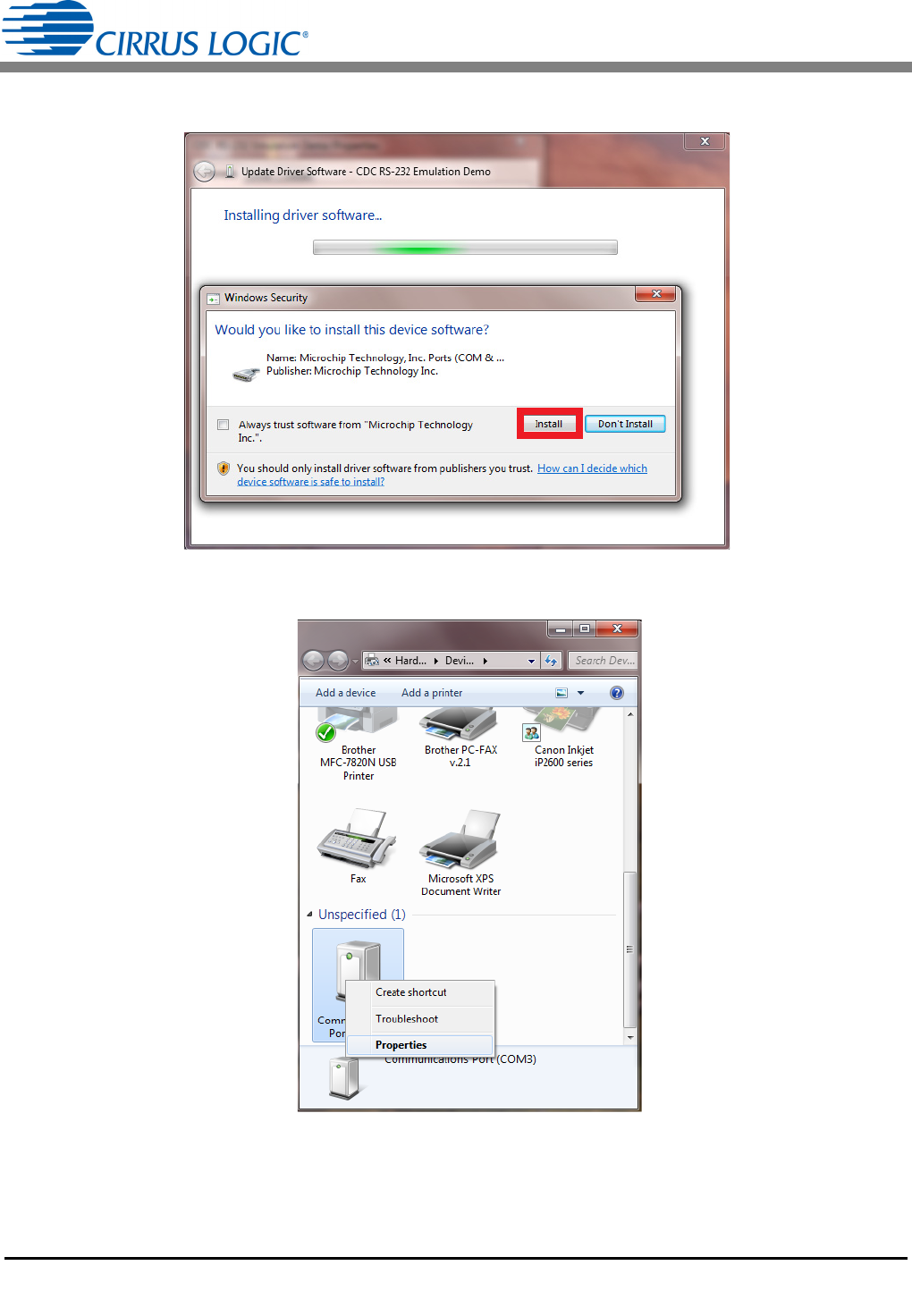
10.
Follow the installation instru
ctions. If warnings are displayed, select to continue anyway
.
1
1.
Right-clic
k the device.
A pop-up menu
is displayed.
Figure 34. Window
s Security Warning
Figure 35. Pop-up Men
u
1
...
...
27
28
29
30
31
...
...
40