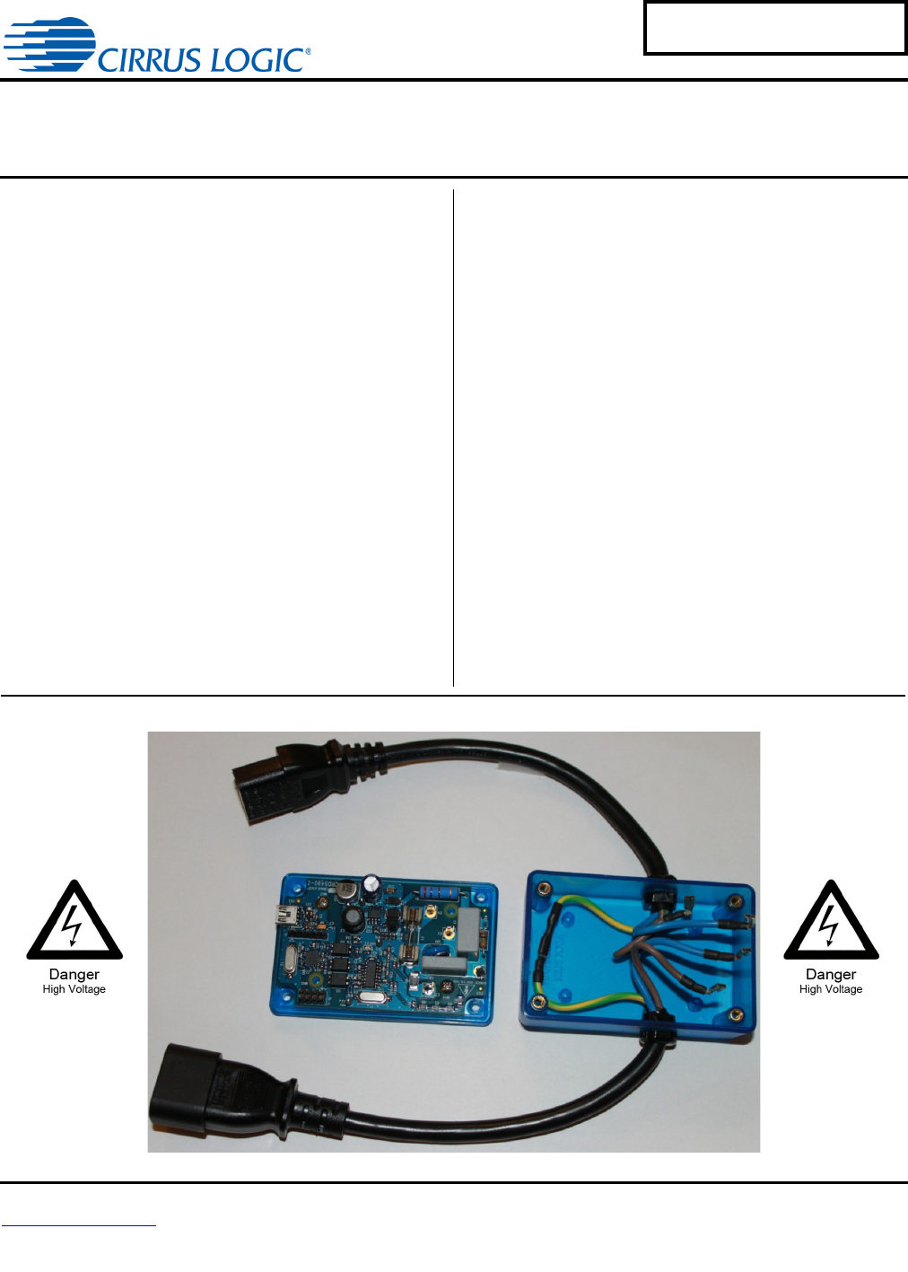
CRD5490-Z CRD5490-Z Power Monitor Features Overview • Easy-to-use Power Monitoring Reference Design – Plug one side into a wall outlet and an electric load into the other side. – Read real time measurements on the PC GUI via USB in seconds. The CRD5490-Z is designed to evaluate the functionality and performance of the CS5490 power/energy measurement device. The CRD5490-Z integrates an efficient and compact AC/DC drop capacitor/buck power supply, voltage and current sensors, and low-cost USB MCU.
CRD5490-Z IMPORTANT SAFETY INSTRUCTIONS Read and follow all safety instructions prior to using this demonstration board. This Engineering Evaluation Unit or Demonstration Board must only be used for assessing IC performance in a laboratory setting. This product is not intended for any other use or incorporation into products for sale. This product must only be used by qualified technicians or professionals who are trained in the safety procedures associated with the use of demonstration boards.
CRD5490-Z 1. CHARACTERISTICS AND SPECIFICATIONS 1.1 Recommended Operating Conditions Parameter Symbol Min Typ Max Unit Line Voltage VAC 90 - 260 V Load Current IRMS - - 15 A Peak Current IPEAK - - 22 A Fundamental Frequency Freq 5 - 2000 Hz TA -40 85 C Symbol Min Typ Max Unit PAC - 0.6 - W - 0.1 - % - 0.1 - % - 0.1 - % Reference Ambient Operating Temperature 1.
CRD5490-Z WARNING High Voltage Hazard When the CRD5490-Z is connected to AC lines, high voltage is present inside the box. Do not remove the protective cover from the CRD5490-Z when power is connected. The evaluation board connects directly to the AC power line and presents a serious risk of electric shock and can cause serious injury or death. Extreme caution needs to be exercised while handling this box. Make sure that the power source is off before wiring any connection.
CRD5490-Z 2.1 Line Voltage Sensor The high-voltage AC line is attenuated using a voltage divider sensor comprised of five 1206 resistors before being supplied to the CS5490 voltage channel input. Figure 2 shows the resistor diagram for line voltage sensing. R1 is actually four large-value resistors, which increases the voltage rating. R2 is one 1K sense resistor. Refer to the vendor’s specifications for voltage compliance. VIN R1 VOUT R2 Figure 2.
CRD5490-Z 2.3 Power Supply The CRD5490-Z contains two separate power supply domains: isolated +5V USB supply and +3.3V non-isolated CS5490 power supply derived from the power line. The +3.3V non-isolated power supply circuit is designed to reduce the overall supply volume by creating a two-stage drop capacitor and buck supply.
CRD5490-Z 3. SOFTWARE OVERVIEW The evaluation board comes with software and a USB cable to link the evaluation board to the PC. The evaluation software was developed with Microsoft® Visual Studio® and was designed to run with Windows XP™ and Windows 7™. The following procedure is based on Windows XP. 3.1 Installation Procedure Follow the steps below to install the GUI and the CDC driver software: 1. Access the following web site: http://www.cirrus.com/en/support. 2. Click the Energy Measurement link. 3.
CRD5490-Z The application will verify system requirements. The Application Install - Security Warning window is displayed. Figure 6. Application Install - Security Warning Window 12. Click the Install button. 13. Follow the instructions of the Microsoft.Net Framework installation. The Microsoft.Net Framework may need to be installed on the system. Internet access may be required to install the Framework or language packs. The download will start automatically.
CRD5490-Z 3.2 Using the Software Before launching the software, ensure that all of the cables connected to the CRD5490-Z are installed (as described in the Hardware Overview section on page 4) and connect the board to an open USB port on the PC using the provided cable. Once the board is powered through the AC line and USB, the software program can be launched. WARNING High Voltage Hazard When the CRD5490-Z is connected to AC lines, high voltage is present inside the box.
CRD5490-Z 3.3.1 Connection Tab The Connection tab displays the USB communication with CRD5490-Z board. At startup, the GUI attempts to establish a connection to the CRD5490-Z to the PC through the last USB device connected. Once the USB communication has been established, the CS5490 serial port will report the Device Revision on the Connection tab.
CRD5490-Z 3.3.2 Quick Measurements Tab The Quick Measurements tab displays reported power data from the CS5490 device in real time as continuous conversions are performed. Refer to the CS5490 data sheet, entitled Two Channel Energy Measurement IC, for more information about continuous conversion. Figure 9. Quick Measurements Tab - Idle Figure 10.
CRD5490-Z The Connection, Graphics, and Quick Measurements tabs may be viewed with the conversions running, but the continuous conversions should be stopped before moving to the Data Table, Calibration, or Register Write/Read tabs. 3.3.2.1 START Button The START button starts continuous conversions execution until the STOP button is clicked. The power measurements are updated with present values in the CS5490 data registers after each conversion.
CRD5490-Z The charts’ scales will automatically adjust for the data captured. To zoom in on a portion of a chart, click in the chart and drag a box over the portion to be enlarged. Scroll bars are displayed in the magnified chart. See Figure 12. Selected Chart Area Selected Chart Area Magnified Figure 12. Graphics Tab with Chart Zoom Example It is recommended to stop conversions before clicking on charts. Transactions are stopped when selecting a chart, and samples may be missed. 3.3.3.
CRD5490-Z 3.3.4 Data Table Tab The Data Table tab displays the CS5490 power information in a table. Stop conversions before viewing the Data Table tab. Figure 13. Data Table Tab 3.3.4.1 Write Table Button The Write Table button writes the full data table to a comma-delimited file (*.csv) using Windows’ standard file window. Select the directory location and filename in the Save As window. 3.3.4.2 Clear Table Button The Clear Table button clears the table.
CRD5490-Z 3.3.5 Calibration Tab The Calibration tab is used to write and display to the CS5490 offset and gain calibration registers. The built-in calibration sequences of the CS5490 that are used to set the calibration register can be initiated from the Calibration tab. AC offset and gain calibration can be performed on the voltage channel, the current channel, or both simultaneously.
CRD5490-Z 3.3.5.1 AC Offset / Gain Register In the AC Offset and Gain fields, the AC offset and gain registers for all channels are displayed in hexadecimal format. These registers can be modified directly by typing values in the fields and then pressing Enter on the keyboard. The AC offset register only affects the current channel's IRMS register values. 3.3.5.2 Performing Calibrations To ensure accurate results, Gain calibration should be performed before AC offset calibration.
CRD5490-Z 4. Confirm that the initial conditions are configured as shown in Figure 17: Figure 17. Calibration Tab with Initial Calibration Configuration 5. Click the Quick Measurements tab to bring it forward, and click the START button. 6. Wait approximately 5 to 10 seconds for the readings to update. 7. Click the STOP button.
CRD5490-Z 8. Record the reference meter measurements after the setup has settled and before calibration is executed. See Figure 18. Figure 18. Calibration Tab with Reference Meter Reading 9. Click the Gain Calibration button. 10. A confirmation message is displayed, as shown in Figure 19. Figure 19.
CRD5490-Z If the calibration conditions (voltage and current) match the reference meter readings, click the Yes button. 11. The gain register values automatically update when the calibration is complete. Figure 20. Calibration Tab with Gain Register Updated After Gain Calibration 12. To confirm results click the Quick Measurements tab to bring it forward, and click the START button. Figure 21. Quick Measurements Tab Showing Results that Should Match the Reference Meter 13.
CRD5490-Z AC Offset Calibrations For AC offset calibration, the CRD5490-Z software clears the offset register before calibration begins. The gain register values are not modified by the software, and the current configuration is used from the prior gain calibration. AC calibration only affects the current channel's IRMS value. 1. Continue from step 13 in the Gain Calibration section on page 16 and keep the AC source on. 2. Remove the AC load. 3. Open the Quick Measurements tab and click the START button. 4.
CRD5490-Z 8. Confirm the load has been removed or turned off, and then click Yes from the CONFIRM LOAD window shown in Figure 23. Figure 23. Calibration Tab with CONFIRM LOAD Window 9. The offset register value automatically updates when the calibration is completed (approximately 5 seconds). The AC Offset register value should change. Figure 24.
CRD5490-Z 10. To confirm results, click the Quick Measurements tab to bring it forward, and click the START button. Figure 25. Confirm IRMS Reduced After AC Offset Calibration Results should show a reduction in the IRMS value without the load.
CRD5490-Z 3.3.6 Register Write/Read Tab The Register Write/Read tab allows access to the CS5490 registers directly. See Figure 26. Figure 26. Register Write/Read Tab - Read There are two types of transactions: Write and Read. The CS5490 memory is organized by pages. In order to properly write a register, it is necessary to set the Page, Address, and Data field and then click the Write button. To read a register it is necessary to set the Page and Address and then click the Read button.
CRD5490-Z 4. REVISION HISTORY Revision Date RD1 APR 2012 24 Changes Initial Release.
CRD5490-Z APPENDIX 1: CRD5490 GUI REMOVAL Follow the steps below to remove the CS5490 GUI software: 1. From the Start menu, click Control Panel. The Control Panel window is displayed. Figure 27. Control Panel Window 2. Click Add or Remove Programs. The Add or Remove Programs window is displayed. 3. Highlight to select the Cirrus Power Monitor (CRD5490) item, as shown in Figure 28. Figure 28. Add or Remove Programs with Cirrus Power Monitor (CRD5490) Displayed 4.
CRD5490-Z APPENDIX 2: CDC DRIVER INSTALLATION This Appendix includes the procedures for installing the CDC driver for both Windows 7 and Windows XP. 2.1 Installing the CDC Driver Using Windows 7 Follow the instructions below to install the CDC driver on the Windows 7 operating system. 1. Connect the provided USB cable from the CRD5490-Z to the PC. Windows will recognize the device. 2. From the Start menu, select Devices and Printers. 3. Right-click the CDC RS-232 Emulation Demo icon. Figure 29.
CRD5490-Z 5. Click the Properties button Figure 30. CDC RS-232 Emulation Demo Properties Window 6. Click the General tab to bring it forward, and click the Change Settings button. Figure 31.
CRD5490-Z 7. Click the Update Driver button. Figure 32. General Tab with the Update Driver Button Active The Update Driver Software CDC RS-232 Emulation Demo panel is displayed. 8. Click Browse my computer for driver software. Figure 33. Update Driver Software Panel Options (Partially Illustrated) 9. Select the extracted file location, then select the. \inf\win2K_winxp\ directory.
CRD5490-Z 10. Follow the installation instructions. If warnings are displayed, select to continue anyway. Figure 34. Windows Security Warning 11. Right-click the device. A pop-up menu is displayed. Figure 35.
CRD5490-Z 12. Click Properties. The Communications Port (COM3) Properties window is displayed. Figure 36. Communications Port (COM3) Properties Window The next time this device is used, it will be recognized, and installing the driver will not be necessary. 2.2 Installing the CDC Driver Using Windows XP Follow the instructions below to install the CDC driver on the Windows XP operating system. 1. Connect the provided USB cable from the CRD5490-Z to the PC.
CRD5490-Z 2. Locate the driver information file provided with the software installation and browse to the driver file: \ inf \ win2K_winxp \ Figure 38. Browse For Folder Window 3. Click the OK button. 4. Click the Next and follow the instructions. If warnings are displayed, select to continue. Figure 39.
CRD5490-Z 5. When the installation is complete, click the Finish button. Figure 40. Found New Hardware Wizard Window with a Message that Installation Is Complete The next time this device is used on the computer, it will be recognized, and the installation of the driver will not be necessary.
CRD5490-Z APPENDIX 3: NON-FULL SCALE GAIN CALIBRATION When resources are limited, it may be necessary to provide non-full-scale amplitudes and perform built-in calibration. To perform a non-full-scale calibration, the initial gain register conditions of the device must be identified before calibration. Usually, initial gain register conditions are set to a default value of one, but this is not required.
CRD5490-Z Current Scale Register To perform calibration with less than full scale load without using the above procedure, it is possible to set the current channel's Scale register. The current channel calibration data path contains a Scale register (page 18, address 63) that can be adjusted before calibration to accommodate the non-full-scale load. I REF 23 I SCALE = ------------ 0.
DS988RD1 4.
5. BILL OF MATERIALS BOM#: 505-00554-Z1 Rev: A2 Date Generated: 03/21/2012 Line Item Part Cirrus PN Ass 0001 P 011-00068-Z1 0002 P 011-00051-Z1 0003 P 012-00198-Z1 BOM Desc: PWA CRD5490-Z-NPb Rev Description Status Qty UM Ref Desg Man'f Man'f PN A A A CAP 0.
DS988RD1 BOM#: 505-00554-Z1 Rev: A2 Date Generated: 03/21/2012 Line Item Part Cirrus PN Ass 0030 P 031-00054-Z1 0031 P 020-06493-Z1 BOM Desc: PWA CRD5490-Z-NPb Rev Description Status Qty UM Ref Desg Man'f A A RES 270 OHM 3W ±5% MTL FLM NPb AXL RES 0.
6. LAYOUT Figure 43.
DS988RD1 Figure 44.
Figure 45.