
Instruction Manual
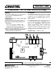
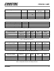
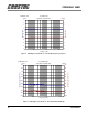
Table Of Contents
- CRD4299-1 AMR: CrystalClear™ AC '97 AMR Reference Design
- Features
- Description
- TABLE OF CONTENTS
- LIST OF FIGURES
- LIST OF TABLES
- Contacting Cirrus Logic Support
- 1. GENERAL INFORMATION
- 2. REFERENCE DESIGN FEATURES
- 3. SCHEMATIC DESCRIPTION
- 4. GROUNDING AND LAYOUT
- 5. AUDIO PERFORMANCE EVALUATION
- Table 1. Reference Designators
- Table 2. Microphone Support Specifications
- Table 3. Full Duplex Specifications
- Table 4. Analog Mixer, Line In to Line Out Specifications
- Table 5. Analog Mixer, Mic In to Line Out Specifications
- 5.1 Plots
- Figure 1. Full Duplex (A-D-PC-D-A): Line In/Out Frequency Response
- Figure 2. Full Duplex (A-D-PC-D-A): Line In/Out Dynamic Range
- Figure 3. Full Duplex (A-D-PC-D-A): Line In/Out THD+N vs. Frequency
- Figure 4. Analog Mixer (A-A): Line In/Out Frequency Response
- Figure 5. Analog Mixer (A-A): Line In/Out Dynamic Range
- Figure 6. Analog Mixer (A-A): Line In/Out THD+N vs. Frequency
- Figure 7. Analog Mixer (A-A): Mic In/Line Out Frequency Response
- Figure 8. Analog Mixer (A-A): Mic In/Line Out Dynamic Range
- Figure 9. Analog Mixer (A-A): Mic In/Line Out THD+N vs. Frequency
- Figure 10. Analog Mixer (A-A): Line In/Out Crosstalk vs. Frequency
- 6. REFERENCES
- 7. SCHEMATIC, LAYOUT, AND BRACKET DRAWINGS
- 8. BILL OF MATERIALS

CRD4299-1 AMR
6 DS319RD1A1
- Pin 3 : Common return
- Pin 4 : Right Channel
2.4.6 Aux In
• Internal 4-pin (0.1 inch center) right-angled
connector
•Wired as:
- Pin 1 : Left Channel
- Pin 2 : Analog Ground
- Pin 3 : Analog Ground
- Pin 4 : Right Channel
• Maximum input level: 2 Vrms
2.4.7 Video In
• Internal 4-pin (0.1 inch center) right-angled
connector
- Pin 1 : Left Channel
- Pin 2 : Analog Ground
- Pin 3 : Analog Ground
- Pin 4 : Right Channel
• Maximum input level: 2 Vrms
2.4.8 Modem Audio Connection
The modem audio connection can be made through
the internal 4-pin (0.1 inch center) right-angled
connector. This connector carries both a mono in-
put and a mono output.
• Internal 4 pin header (0.1 inch center)
- Pin 1 : Mono Out (to modem)
- Pin 2 : Analog Ground
- Pin 3 : Analog Ground
- Pin 4 : Phone In (from modem)
• Maximum input level: 1 Vrms
• Maximum output level: 1 Vrms
• Minimum load impedance: 10 kΩ
3. SCHEMATIC DESCRIPTION
Figures 11 through 17 show the schematics for the
CRD4299-1 AMR card. This section will describe
particular pages of the schematic that need to be
discussed.
3.1 Figure 11: Block Diagram
The block diagram is an interconnection overview
between schematic pages.
3.2 Figure 12: AMR Bus Interface
The +5 V power pin is decoupled through C1 and
supplies power for the SPDIF_OUT circuit. All
ground pins are tied to digital ground except for B2,
which is tied to analog ground.
The AC-link, which consists of ASDOUT, ARST#,
ASYNC, ASDIN, and ABITCLK, transfers digital
audio data between the audio codec and the host.
PC_BEEP_BUS routes the beep/speaker signal
from the motherboard to the audio subsystem, for
use in hearing POST codes (refer to the Intel Au-
dio/Modem Riser Specification [2]).
The PRIMARY_DN# signal indicates the presence
or the absence of a primary codec on the mother-
board. The MSTRCLK is the 24.576 MHz master
clock for the AC ‘97 link. Populate R51 when the
Codec is the primary codec. Populate R50 when the
Codec is the secondary codec.
The CS4297 does not support S/PDIF. Iin this case,
R3 should be populated so the S/PDIF signal orig-
inates from the AMR bus. For a CS4297A/99, by
populating R2 instead of R3, the S/PDIF signal
originates from the codec, bypassing the AMR bus.
3.3 Figure 13: Power Supply
The CS4299 requires both a digital +3.3 V and an
analog +5 V supply. The digital power is supplied
from the AMR bus. A separate regulator is recom-
mended for the analog voltage supply to provide
good audio signal quality. A Motorola MC78L05
regulates the +12 V supply from the AMR bus