
Instruction Manual
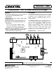
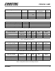
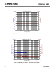
Table Of Contents
- CRD4299-1 AMR: CrystalClear™ AC '97 AMR Reference Design
- Features
- Description
- TABLE OF CONTENTS
- LIST OF FIGURES
- LIST OF TABLES
- Contacting Cirrus Logic Support
- 1. GENERAL INFORMATION
- 2. REFERENCE DESIGN FEATURES
- 3. SCHEMATIC DESCRIPTION
- 4. GROUNDING AND LAYOUT
- 5. AUDIO PERFORMANCE EVALUATION
- Table 1. Reference Designators
- Table 2. Microphone Support Specifications
- Table 3. Full Duplex Specifications
- Table 4. Analog Mixer, Line In to Line Out Specifications
- Table 5. Analog Mixer, Mic In to Line Out Specifications
- 5.1 Plots
- Figure 1. Full Duplex (A-D-PC-D-A): Line In/Out Frequency Response
- Figure 2. Full Duplex (A-D-PC-D-A): Line In/Out Dynamic Range
- Figure 3. Full Duplex (A-D-PC-D-A): Line In/Out THD+N vs. Frequency
- Figure 4. Analog Mixer (A-A): Line In/Out Frequency Response
- Figure 5. Analog Mixer (A-A): Line In/Out Dynamic Range
- Figure 6. Analog Mixer (A-A): Line In/Out THD+N vs. Frequency
- Figure 7. Analog Mixer (A-A): Mic In/Line Out Frequency Response
- Figure 8. Analog Mixer (A-A): Mic In/Line Out Dynamic Range
- Figure 9. Analog Mixer (A-A): Mic In/Line Out THD+N vs. Frequency
- Figure 10. Analog Mixer (A-A): Line In/Out Crosstalk vs. Frequency
- 6. REFERENCES
- 7. SCHEMATIC, LAYOUT, AND BRACKET DRAWINGS
- 8. BILL OF MATERIALS

CRD4299-1 AMR
DS319RD1A1 5
MC78L05 regulates the AMR +12 V supply down
to provide a clean +5 V analog supply for the
CS4299. The MC78L05 regulator can provide ade-
quate current, which is enough for the CS4299 and
associated analog circuitry.
2.3 Analog I/O
The CS4299 has many analog inputs and outputs
that may or may not be used depending on the sys-
tem’s application. Unused inputs should be tied to
Vrefout (pin 28) or AC coupled via a 0.1 µF capac-
itor to the analog ground plane. The analog section
contains the components for a headphone amplifi-
er. The Modem Audio, CD In, Audio In, and Aux
In headers are also part of the Analog I/O section.
The header and its associated components may or
may not be necessary depending on the audio in-
puts implemented.
2.4 Audio I/O
A full feature set of the CS4299’s analog I/O and
digital out is represented on the reference design
card through internal and external connectors:
•Line Out
• Headphone Out
•Line In
•Mic In
• CD Audio In
• Aux In
•Video In
• Modem Audio connection
• Optical Digital Out
Four external 1/8" jacks, one external TOS-LINK
jack, and four internal header connections are used
for analog and digital inputs and outputs.
2.4.1 Line Out
The output of the CS4299 is capable of driving im-
pedances greater than 10 kΩ with a maximum out-
put voltage of 1 Vrms. The Line Out connection is
made via an external 1/8" jack.
• Maximum output level: 1 Vrms
2.4.2 Headphone Out
An external 1/8" jack is provided for a headphone
connection. This output is driven by an amplifier
for low impedance loads such as 32 Ω headphones.
• Maximum output level: 2.0 Vrms (no load);
1.5 Vrms (32 Ω load)
• Maximum output power: 70 mW/channel
(32 Ω load)
2.4.3 Line In
The Line In 1/8" jack provides an input to the Line
In pins of the CS4299.
• Maximum input level: 2 Vrms
2.4.4 Mic In
The Microphone In 1/8" jack provides an input to a
microphone pre-amplifier circuit that applies 18 dB
of gain to the signal.
• Maximum input level:
- Microphone Boost enabled: 12.5 mVrms
- Microphone Boost disabled: 125 mVrms
• Supports 3-pin electret (power on ring) and 2-
pin dynamic microphones
2.4.5 CD Audio In
The CD Audio input provides a 4-pin (0.1 inch cen-
ter) right-angled connector that is compatible with
the SONY standards and ATAPI.
• Maximum input level: 2 Vrms
• Pseudo differential input using the CD Com-
mon pin as the ground
• 0.1 inch connector wired as:
- Pin 1 : Left Channel
- Pin 2 : Common return