
Instruction Manual
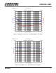
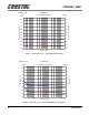
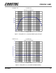
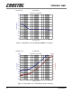
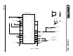
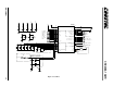
Table Of Contents
- CRD4299-1 AMR: CrystalClear™ AC '97 AMR Reference Design
- Features
- Description
- TABLE OF CONTENTS
- LIST OF FIGURES
- LIST OF TABLES
- Contacting Cirrus Logic Support
- 1. GENERAL INFORMATION
- 2. REFERENCE DESIGN FEATURES
- 3. SCHEMATIC DESCRIPTION
- 4. GROUNDING AND LAYOUT
- 5. AUDIO PERFORMANCE EVALUATION
- Table 1. Reference Designators
- Table 2. Microphone Support Specifications
- Table 3. Full Duplex Specifications
- Table 4. Analog Mixer, Line In to Line Out Specifications
- Table 5. Analog Mixer, Mic In to Line Out Specifications
- 5.1 Plots
- Figure 1. Full Duplex (A-D-PC-D-A): Line In/Out Frequency Response
- Figure 2. Full Duplex (A-D-PC-D-A): Line In/Out Dynamic Range
- Figure 3. Full Duplex (A-D-PC-D-A): Line In/Out THD+N vs. Frequency
- Figure 4. Analog Mixer (A-A): Line In/Out Frequency Response
- Figure 5. Analog Mixer (A-A): Line In/Out Dynamic Range
- Figure 6. Analog Mixer (A-A): Line In/Out THD+N vs. Frequency
- Figure 7. Analog Mixer (A-A): Mic In/Line Out Frequency Response
- Figure 8. Analog Mixer (A-A): Mic In/Line Out Dynamic Range
- Figure 9. Analog Mixer (A-A): Mic In/Line Out THD+N vs. Frequency
- Figure 10. Analog Mixer (A-A): Line In/Out Crosstalk vs. Frequency
- 6. REFERENCES
- 7. SCHEMATIC, LAYOUT, AND BRACKET DRAWINGS
- 8. BILL OF MATERIALS
CRD4299-1 AMR
18 DS319RD1A1
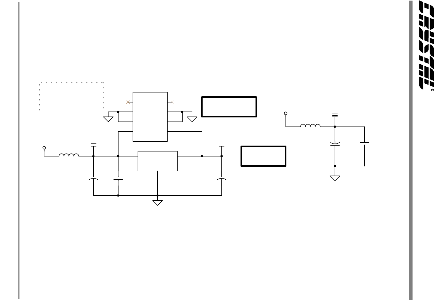
POWER SUPPLIES
Connect AGND to DGND with a 50 mil trace near the 4297
Connect CGND to DGND with a 50 mil trace near the finger
edge of the board.
SURFACE MOUNT
POPULATION
OPTION
PIN IN HOLE
POPULATION
OPTION
Do not populate U5
+12VD
+12VA
AGND
+5VA
AGNDAGND
-12VA
-12VD
AGND
U5
MC78L05ACD
18
2
36
7
5 4
VOUTVIN
GND1
GND2GND3
GND4
NC2 NC1
C71
0.1uF
Z5U
L2
31@100MHz
U4
MC78L05
3
2
1
IN
GND
OUT
+
C70
100uF
ELEC
+
C72
10uF
ELEC
L1
31@100MHz
C74
0.1uF
Z5U
+
C73
100uF
ELEC
Figure 13. Power Supplies