
Instruction Manual


Table Of Contents
- Features
- Description
- 1. General information
- 2. Schematic Description
- 3. Grounding and Layout
- 4. References
- 4.1 ADDENDUM
- Figure 1. Block Diagram
- Figure 2. CS4202 Audio Codec
- Figure 3. Analog Inputs
- Figure 4. Center Channel, Surround, and Sub-Woofer Outputs
- Figure 5. Front Channel and Headphone Sense Output
- Figure 6. S/PDIF Optical Output
- Figure 7. CNR Connector
- Figure 8. Phase Locked Loop
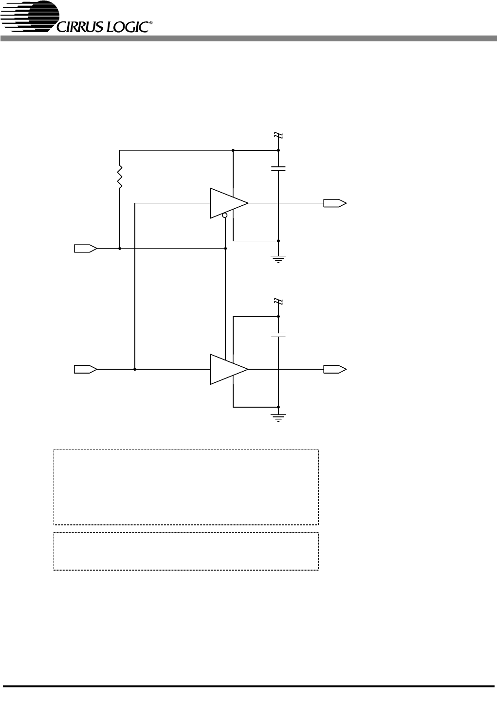
- Figure 9. Auto Demotion and Serial Buffers
- Figure 10. PCB Layout: Top Assembly Drawing
- Figure 11. PCB Layout: Top Layer
- Figure 12. PCB Layout: Bottom Layer
- Figure 13. PCB Layout: Drill Drawing
- Figure 14. PCB Layout: Top Silkscreen
- 4.1 ADDENDUM
- 5. bill of materials
CRD4202-1
DS549RD1A1 15
U7
TC7SZ125FU
5
1
2 4
3
U8
TC7SZ126FU
5
1
2 4
3
C70
0.1uF
X7R
C71
0.1uF
X7R
R54
1K
+3.3VD
DGND
DGND
+3.3VD
PRIM_DN#
ASDIN1
ASDIN0ASDIN
R54 = 1K forces
motherboard codec(s)
to be held in RESET
DO NOT use this circuit for motherboard designs. This circuit is strictly for CNR cards.
Replace R54 with 100K for automatic demotion
when used with primary motherboard codec(s).
For motherboard designs:
connect ASDIN to ASDIN0 if primary codec,
connect ASDIN to ASDIN1 if secondary codec.
Figure 9. Auto Demotion and Serial Buffers