
Instruction Manual

CRD1631-10W
DS1005RD2 15
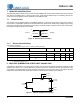
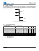
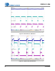
8.1 Flyback Transformer
The flyback transformer stage is a quasi-resonant peak current-regulated DC-DC converter capable of delivering
the highest possible efficiency with constant current output while minimizing line frequency ripple. The auxiliary wind-
ing is used for zero-current detection and overvoltage protection.
Figure 12. Flyback Transformer Schematic
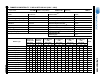
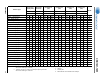
8.1.1 Electrical Specifications
Characteristics conditions:
• Operating temperature range: -25 °C to +120 °C (including coil heat)
Notes: 9. Time = 2sec.
10. Measured across pins 5 and 4.
11. Measured across pins 10 and 9.
12. Measured across pins 3 and 2.
Parameter Condition Symbol Min Typ Max Unit
Flyback Transformer
Electrical Strength (Note 9)
f
operate
=50/60Hz
-4K-V
RMS
Primary Inductance (Note 10)
f
resonant
=10kHz, 0.3V at
20°C
L
P
-9.7-mH
Primary Leakage Inductance (Note 10)
f
resonant
=10kHz, 0.3V at
20°C
L
K
- 138 - H
Primary DC Resistance (Note 10)
t
DCR
=20°C
-22.7-
Secondary DC Resistance (Note 11)
t
DCR
=20°C
-0.3-
Auxiliary DC Resistance (Note 12)
t
DCR
=20°C
-1-
144T
#38 AWG
144T
#38 AWG
36T TWR
#29 AWG
Prim a ry
Secondary
5
1
4
10
9
8T
#40 AWG
2
Auxilia ry
3