
Instruction Manual

CRD1631-10W
14 DS1005RD2
7. INDUCTOR CONSTRUCTION
The CRD1631-10W includes a critical conduction mode (CRM) boost converter that provides power factor correction
and dimmer compatibility with a constant output current, quasi-resonant flyback stage. The following sections de-
scribe the boost and flyback inductors installed on the CRD1631-10W.
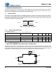
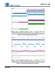
7.1 Boost Inductor
The CS1631 uses an adaptive dimmer compatibility algorithm to control the boost inductor stage, which helps to
ensure dimmer compatibility operation plus enables flicker-free operation with leading-edge, trailing-edge, and dig-
ital dimmers (dimmers with an integrated power supply). The boost auxiliary winding is used for zero-current detec-
tion (ZCD) and supplies power to the CS1631.
Figure 10. Boost Inductor Schematic
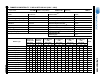
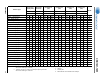
7.1.1 Electrical Specifications
Characteristics conditions:
• Operating temperature range: -25°C to +120°C (including coil heat)
Notes: 7. Measured across pins 3 and 4.
8. Measured across pins 2 and 1.
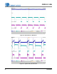
8. NEGATIVE TEMPERATURE COEFFICIENT CONNECTION
Temperature compensation of the LED current requires using an external negative temperature coefficient (NTC)
thermistor (see Figure 11). In typical applications, the NTC is placed on the driver PCB near the heat sinks of the
retrofit lamps. For demonstration purposes, the NTC is integrated on the light engine close to the LEDs to illustrate
temperature compensated LED current and correlated color temperature control system features.
Parameter Condition Symbol Min Typ Max Unit
Boost Inductor
Primary Inductance (Note 7)
f
resonant
=10kHz, 0.3V at 20°C
L
P
-5.6-mH
Primary DC Resistance (Note 7)
t
DCR
=20°C
-29-
Auxiliary DC Resistance (Note 8)
t
DCR
=20°C
-1.9-
3
4
2
1
Primary Auxiliary
560 T
#38 AWG
31 T
#38 AWG
Connect
to 230V
To NTC -
To Red -
To Red +
To White -
To White +
To NTC +
Figure 11. CRD1631 PCBA NTC Connection