
User Manual


CRD1630-10W
DS1004RD2 15
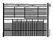
7.2.1 Electrical Specifications
Characteristics conditions:
• Operating temperature range: -25 °C to +120 °C (including coil heat)
Notes: 9. Time = 2sec.
10. Measured across pins 5 and 4.
11. Measured across pins 10 and 9.
12. Measured across pins 3 and 2.
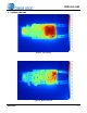
8. NEGATIVE TEMPERATURE COEFFICIENT CONNECTION
Temperature compensation of the LED current requires using an external negative temperature coefficient (NTC)
thermistor (see Figure 12). In typical applications, the NTC is placed on the driver PCB near the heat sinks of the
retrofit lamps. For demonstration purposes, the NTC is integrated on the light engine close to the LEDs to illustrate
temperature compensated LED current and correlated color temperature control system features.
Parameter Condition Sym Min Typ Max Unit
Flyback Transformer
Electrical Strength (Note 9)
f
operate
=50/60Hz
-4K-V
RMS
Primary Inductance (Note 10)
f
resonant
=10kHz, 0.3V at
20°C
L
P
-
3.95
-
mH
Primary Leakage Inductance (Note 10)
f
resonant
=10kHz, 0.3V at
20°C
L
K
-60-H
Primary DC Resistance (Note 10)
t
DCR
=20°C
-
12.8
-
Secondary DC Resistance (Note 11)
t
DCR
=20°C
-0.3-
Auxiliary DC Resistance (Note 12)
t
DCR
=20°C
-
1.6
-
Connect
to 120V
To NTC -
To Red -
To Red +
To White -
To White +
To NTC +
Figure 12. PCBA NTC Connection