
User Manual


CRD1630-10W
14 DS1004RD2
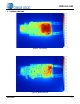
7. INDUCTOR CONSTRUCTION
The CRD1630-10W includes a critical conduction mode (CRM) boost converter that provides power factor correction
and dimmer compatibility with a constant output current, quasi-resonant flyback stage. The following sections de-
scribe the boost and flyback inductors installed on the CRD1630-10W.
7.1 Boost Inductor
The CS1630 uses an adaptive dimmer compatibility algorithm to control the boost inductor stage, which guarantees
dimmer compatibility operation plus enables flicker-free operation with leading-edge, trailing-edge, and digital dim-
mers. The boost auxiliary winding is used for zero-current detection (ZCD) and supplies power to the CS1630.
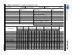
7.1.1 Electrical Specifications
Characteristics conditions:
• Operating temperature range: -25 °C to +120 °C (including coil heat)
Notes: 7. Measured across pins 3 and 4.
8. Measured across pins 2 and 1.
7.2 Flyback Transformer
The flyback transformer stage is a quasi-resonant current-regulated DC-DC Converter capable of delivering the
highest possible efficiency at a constant current while minimizing line frequency ripple. The auxiliary winding is used
for zero-current detection and overvoltage protection.
Parameter Condition Symbol Min Typ Max Unit
Boost Inductor
Primary Inductance (Note 7)
f
resonant
=10kHz, 0.3V at 20°C
L
P
-2-mH
Primary DC Resistance (Note 7)
t
DCR
=20°C
-4.7-
Auxiliary DC Resistance (Note 8)
t
DCR
=20°C
-0.8-
3
4
2
1
P
rimary Auxiliary
240T
#36 AWG
32T
#36 AWG
Figure 10. Boost Inductor Schematic
110T
#36 AWG
110T
#36 AWG
22T
#36 AWG
42T TWR
#27 AWG
P
rimary
Secondary
5
1
4
10
2
Auxiliary
3
9
Figure 11. Flyback Transformer Schematic