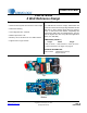
CRD1616-8W CRD1616-8W 8 Watt Reference Design Features General Description • Quasi-resonant Flyback with Constant-current Output The CRD1616-8W reference design demonstrates the performance of the CS1616 single stage dimmable AC/DC LED driver IC with a 250mA output driving 10 LEDs in series. It offers best-in-class dimmer compatibility with leading-edge, trailing-edge, and digital dimmers. The form factor is targeted to fit into many LED bulb applications (GU10, A19, PAR, BR).
CRD1616-8W IMPORTANT SAFETY INSTRUCTIONS Read and follow all safety instructions prior to using this demonstration board. This Engineering Evaluation Unit or Demonstration Board must only be used for assessing IC performance in a laboratory setting. This product is not intended for any other use or incorporation into products for sale. This product must only be used by qualified technicians or professionals who are trained in the safety procedures associated with the use of demonstration boards.
CRD1616-8W 1. INTRODUCTION The CS1616 is a 230VAC quasi-resonant flyback mode dimmable LED controller IC. The CS1616 uses a digital control algorithm that is optimized for high efficiency and >0.9 power factor over a wide input voltage range (207VAC to 253VAC). The CS1616 integrates a dimmer compatibility circuit with a constant output current, quasi-resonant flyback stage.
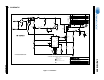
2. SCHEMATIC REV DESCRIPTION DATE A INITIAL RELEASE 12/17/12 ECO1028 A1 CHGD C11 TO KEMET PHE426KJ5220JR05. CHGD C13 TO PANASONIC ECQE4683RJF. CHGD C2 TO KEMET PHE426KJ5470JR05. CORRECTED CONNECTION ON D5. 01/23/13 ECO1029 B INCORPORATED ECO1028 CHANGES TO THE BOARD LAYOUT. 02/05/13 ECO1050 ECO1070 C C1 CHANGED D7, FOOT PRINT CHANGED 02/25/13 04/19/13 ECO1080 D ECO1095 E L1 10mH ' 1N4005 + 1 ( R9 56 Ohm 4 %5 HD04-T 4.7K 2 2W 3 1 R3 C13 MTLPOLY 0.
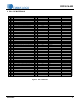
CRD1616-8W 3. BILL OF MATERIALS Item Rev DescripƟon 1 DIODE RECT 400V 0.8A NPB MINIDIP 2 CAP 47uF ±20% 35V AL ELEC NPb RAD 3 CAP 0.047uF ±5%LS 400V MTL NPb RAD 4 A CAP 2200pF ±10% 2KV CERAMIC NPb TH 5 CAP 680uF ±20% 35V AL ELEC NPb RAD 6 CAP 1uF ±10% 25V X7R CER NPb 0603 7 CAP 0.022uF ±5%LS 400V MTL NPb RAD 8 CAP 0.
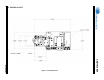
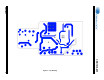
4. BOARD LAYOUT CRD1616-8W DS1003RD4 Figure 3.
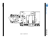
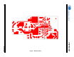
DS1003RD4 7 CRD1616-8W Figure 4.
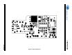
CRD1616-8W DS1003RD4 Figure 5.
DS1003RD4 9 CRD1616-8W Figure 6.
CRD1616-8W DS1003RD4 Figure 7.
CRD1616-8W 5. THERMAL IMAGING Figure 8. Top Thermal Figure 9.
CRD1616-8W 6. DIMMER COMPATIBILITY - A19 WITH CS1616 (230V/50HZ) Input Power 8.34W 718/864 Date 1/14/2013 Power Factor1,5 Vendor Cirrus Logic EN55015 Compliant (Y/N) Dimmer Compatibility 81.7% Efficiency 0.95 Y 1,5 Input Voltage 230V/50Hz Nominal Input Power (W) 8.34 Form Factor A19 Maximum Input Power (W)1,5 8.5 Model # CRD1616-8W Output Voltage (V)1,3 27.
CRD1616-8W Dimmer Type Flicker Free Steady-state Monotonic Dimming Max IOUT (mA) Min IOUT (mA) # of Lamps # of Lamps # of Lamps # of Lamps Total 1 5 10 1 5 10 1 5 10 1 5 10 Lonon - Leading Edge Y Y Y Y Y Y 248 248 251 3 3 3 24 Lutron - Leading Edge Y N N Y Y Y 249 248 249 3 3 3 14 Lutron - Leading Edge Y Y N Y Y Y 244 245 246 3 3 3 19 MK - Leading Edge Y N N Y Y Y 250 251 250 3 3 3 14 N&L - Trailing Edge N Y Y N N N 213 2
CRD1616-8W 7. INDUCTOR CONSTRUCTION The CRD1616-8W provides power factor correction and dimmer compatibility with a constant output current, quasiresonant flyback stage. The following sections describe the flyback transformer installed on the CRD1616-8W. 7.1 Flyback Transformer The flyback transformer stage is a quasi-resonant peak current-regulated DC-DC converter capable of delivering the highest possible efficiency with constant current output while minimizing line frequency ripple.
CRD1616-8W 8. PERFORMANCE PLOTS 0.3 Output Current (A) 0.28 0.26 0.24 0.22 0.2 207 211 215 219 223 227 230 233 237 241 245 249 253 245 249 253 Line Voltage (V) Figure 11. Output Current vs Line Voltage 85 84 83 Efficiency (%) 82 81 80 79 78 77 76 75 207 211 215 219 223 227 230 233 237 241 Line Voltage (V) Figure 12.
CRD1616-8W 1.00 0.99 0.98 Power Factor 0.97 0.96 0.95 0.94 0.93 0.92 0.91 0.90 207 211 215 219 223 227 230 233 237 241 245 249 253 Line Voltage (V) Figure 13. Power Factor vs Line Voltage 20 19 18 THD (%) 17 16 15 14 13 12 11 10 207 211 215 219 223 227 230 233 237 241 245 249 253 Line Voltage (V) Figure 14.
CRD1616-8W 0.3 Output Current (A) 0.25 0.2 Leading Edge 0.15 Trailing Edge 0.1 0.05 0 30 40 50 60 70 80 90 100 110 120 130 140 150 160 170 180 Dim Angle (°) Figure 15.
CRD1616-8W Figure 16. No-dimmer Mode, Startup, 230 VAC Figure 17.
CRD1616-8W Figure 18. Flyback FET Q3, 230VAC Figure 19.
CRD1616-8W Figure 20. Flyback FET Q3, 230VAC (with Zoom In) Figure 21.
CRD1616-8W Figure 22.
CRD1616-8W 9. CONDUCTED EMI Device Under Test: CRD1616-8W-Z Operating Conditions: NOMINAL Test Specification: EN55022:2010 Operator Name: CAL Scan Settings (1 Range) Frequencies Receiver Settings Start Stop Step Res BW M-Time Atten Preamp 150kHz 30MHz 4.5kHz 9kHz (6dB) 50ms Auto Off Final Measurement Detectors: QP, AV Peaks: 25 Meas Time: See scan settings Acc. Margin: 12dB Figure 23.
CRD1616-8W 10.