
User Manual


Table Of Contents
CDB8421
DS641DB3 5
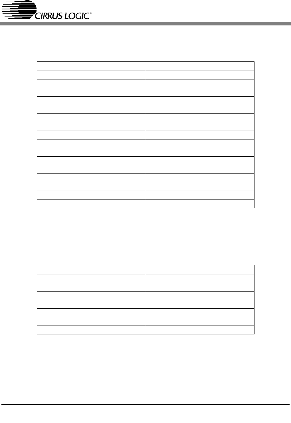
Switch S2 controls the interface format of the CS8406 and the CS8421 output port. The func-
tions for switches S2[3:0] are detailed in Table 3.
Switch S3 controls the interface format of the CS8416 and the CS8421 input port. The func-
tions for switches S3[2:0] are detailed in Table 4.
S2[3:0] CS8421 Output Configuration
0000 I²S 16-bit Data
0001 I²S 20-bit Data
0010 I²S 24-bit Data
0011 I²S 32-bit Data
0100 Left Justified 16-bit Data
0101 Left Justified 20-bit Data
0110 Left Justified 24-bit Data
0111 Left Justified 32-bit Data
1000 Right Justified 16-bit Data
1001 Right Justified 20-bit Data
1010 Right Justified 24-bit Data
1011 Right Justified 32-bit Data
1100 TDM Mode, 16-bit Data
1101 TDM Mode, 20-bit Data
1110 TDM Mode, 24-bit Data
1111 TDM Mode, 32-bit Data
Table 3. Switch S2, Serial Output Formats
S3[2:0] CS8421 Output Configuration
000 I²S up to 32-bit Data
001 Left Justified up to 32-bit Data
010 Right Justified 16-bit Data
011 Right Justified 20-bit Data
100 Right Justified 24-bit Data
101 Right Justified 32-bit Data
110 Left Justified 24-bit Data
Table 4. Switch S3, Serial Input Formats