
Manual


CDB61880
DS450DB1 19
6.2 E1 120 Ω
ΩΩ
Ω Mode Setup
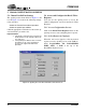
Table 5 shows the position of the different switches
and jumpers used to set up the CDB61880 evalua-
tion board to operate in E1 120 Ω Hardware, Serial
Host and Parallel Host operational modes. Before
selecting Host mode, the switches in Table 5 in
bold should be set to the position stated.
7. Set to “NC” to disable receiver Internal line impedance matching function. The external resistors for all
eight receivers must be changed to 15
Ω
to properly match the input line impedance.
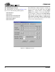
Table 5. E1 120 Ω
ΩΩ
Ω Operational Mode Switch/Jumper Position
Switches/Jumpers Hardware Serial Host (Note 3) Parallel Host (Note 3)
S15 (MODE) HARDWARE SERIAL HOST PARALLEL HOST
S1 (0) LOOP FUNCTION NONE NONE
S2 (1) LOOP FUNCTION NONE NONE
S3 (2) LOOP FUNCTION NONE NONE
S4 (3) LOOP FUNCTION NONE NONE
S5 (4) LOOP FUNCTION NONE NONE
S6 (5) LOOP FUNCTION NONE NONE
S7 (6) LOOP FUNCTION NONE NONE
S8 (7) LOOP FUNCTION NONE NONE
S9 #1 (MOT_\INTL) HIGH OPEN MOTOROLA/INTEL
S9 #2 (MUX) LOW (Note 4) OPEN MUX/NON-MUX
S9 #3 (A4) LOW (Note 5) OPEN OPEN
S9 #4 (A3) LOW (Note 5) OPEN OPEN
S9 #5 (A2) LOW (Note 5) OPEN OPEN
S9 #6 (A1) LOW (Note 5) OPEN OPEN
S9 #7 (A0) LOW (Note 5) OPEN OPEN
S10 (JASEL) ANY POSITION OPEN OPEN
S11 (CBLSEL) NC (Note 7) NC NC
J13 (VLOGIC) 3 V 3 V 3 V
J1 (MCLK) OSCILLATOR OSCILLATOR OSCILLATOR
J93 (CLKE) OPEN OPEN OPEN
J23 (TXOE) OPEN OPEN OPEN