
User Manual


Table Of Contents
- Features
- Table of Contents
- List of Figures
- 1. Hardware
- 2. Software
- 2.1 Installation Procedure
- 2.2 Using the Software
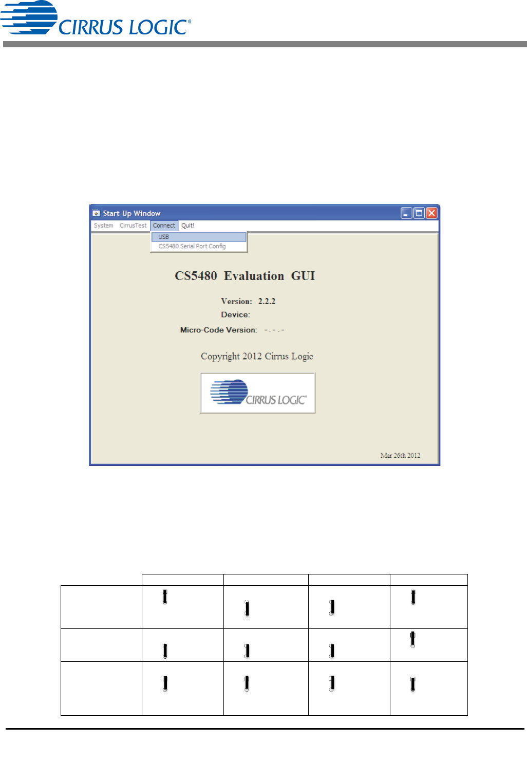
- 2.3 Start-up Window
- 2.4 Connect Menu
- 2.5 System Menu
- 2.5.1 Setup Window
- 2.5.1.1 Refresh Screen Button
- 2.5.1.2 Reset DUT Button
- 2.5.1.3 Save Config and Load Config Buttons
- 2.5.1.4 CS5480 MCLK Frequency
- 2.5.1.5 Configuration Registers
- 2.5.1.6 Pulse Control Register
- 2.5.1.7 Pulse Width and Pulse Rate Registers
- 2.5.1.8 Phase Compensation
- 2.5.1.9 Integrator Gain, System Gain
- 2.5.1.10 Sample Count, Cycle Count, Settle Time
- 2.5.1.11 Epsilon
- 2.5.1.12 ZXNUM
- 2.5.1.13 Mask Register
- 2.5.1.14 Temperature Registers
- 2.5.1.15 Zero-crossing Level and No Load Threshold
- 2.5.1.16 V1/V2 Sag, V1/ V2 Swell, and I1/I2 Overcurrent Registers
- 2.5.1.17 Channel Selection Level, Channel Select Minimum Amplitude, and Voltage Fixed RMS Reference Registers
- 2.5.1.18 Register Checksum, SerialCtrl Registers
- 2.5.1 Setup Window
- 2.6 Calibration Window
- 2.7 Conversion Window
- 2.8 Cirrus Test Window
- 2.8.1 Data Collection Window
- 2.8.1.1 Time Domain / FFT/ Histogram Selector
- 2.8.1.2 Config Button
- 2.8.1.3 Collect Button
- 2.8.1.4 Output Button
- 2.8.1.5 Zoom Button
- 2.8.1.6 Channel Select Button
- 2.8.1.7 Output Button & Window
- 2.8.1.8 Configuration Window
- 2.8.1.9 Collecting Data Sets
- 2.8.1.10 Analyzing Data
- 2.8.1.11 Histogram Information
- 2.8.1.12 Frequency Domain Information
- 2.8.1.13 Time Domain Information
- 2.8.2 Data Collection to File Window
- 2.8.3 Setup and Test Window
- 2.8.1 Data Collection Window
- Appendix A. Bill Of Materials
- Appendix B. Schematics
- Appendix C. Layer Plots
CDB5480U
8 DS893DB5
1.4 Digital Section
The digital section contains the microcontroller, USB interface, LCD, optical isolation, JTAG header, reset
circuitry, and external interface headers (J17 and J19). The microcontroller interfaces the UART or SPI of
the CS5480 with the USB connection to the PC, enabling the GUI software to access all of the CS5480
registers and functions.
1.4.1 Serial Port Selection
Communication to the CS5480 is provided through two serial port options — UART or SPI. It is necessary
to establish communication with the MCU before establishing a serial port communication protocol with
the CS5480 (see Figure 5).
Figure 5. MCU Connection Window
For UART communication, place the SSEL jumper to the UART position via J16, and select UART in the
serial port selection window. To enable SPI communications, place the SSEL jumper to the SPI position
via J16 and select SPI in the serial port selection window. Table 3 provides the serial communication
options on the CDB5480U board.
Table 3. Serial Communication Options
J16 J18 J20 J50
UART
Ƒ UART
ż SSEL
ż SPI
(default)
Ƒ OPTO
ż RX
ż DIGITAL
(default)
Ƒ OPTO
ż TX
ż DIGITAL
(default)
Ƒ VDDA
ż EN2
ż GND
(default)
SPI
Ƒ UART
ż SSEL
ż SPI
Ƒ OPTO
ż RX
ż DIGITAL
Ƒ OPTO
ż TX
ż DIGITAL
Ƒ VDDA
ż EN2
ż GND
Low speed
UART
(4800 Baud Max)
Ƒ UART
ż SSEL
ż SPI
Ƒ OPTO
ż RX
ż DIGITAL
Ƒ OPTO
ż TX
ż DIGITAL
Ƒ VDDA
ż EN2
ż GND