
User Manual


Table Of Contents
- Features
- Table of Contents
- List of Figures
- 1. Hardware
- 2. Software
- 2.1 Installation Procedure
- 2.2 Using the Software
- 2.3 Start-up Window
- 2.4 Connect Menu
- 2.5 System Menu
- 2.5.1 Setup Window
- 2.5.1.1 Refresh Screen Button
- 2.5.1.2 Reset DUT Button
- 2.5.1.3 Save Config and Load Config Buttons
- 2.5.1.4 CS5480 MCLK Frequency
- 2.5.1.5 Configuration Registers
- 2.5.1.6 Pulse Control Register
- 2.5.1.7 Pulse Width and Pulse Rate Registers
- 2.5.1.8 Phase Compensation
- 2.5.1.9 Integrator Gain, System Gain
- 2.5.1.10 Sample Count, Cycle Count, Settle Time
- 2.5.1.11 Epsilon
- 2.5.1.12 ZXNUM
- 2.5.1.13 Mask Register
- 2.5.1.14 Temperature Registers
- 2.5.1.15 Zero-crossing Level and No Load Threshold
- 2.5.1.16 V1/V2 Sag, V1/ V2 Swell, and I1/I2 Overcurrent Registers
- 2.5.1.17 Channel Selection Level, Channel Select Minimum Amplitude, and Voltage Fixed RMS Reference Registers
- 2.5.1.18 Register Checksum, SerialCtrl Registers
- 2.5.1 Setup Window
- 2.6 Calibration Window
- 2.7 Conversion Window
- 2.8 Cirrus Test Window
- 2.8.1 Data Collection Window
- 2.8.1.1 Time Domain / FFT/ Histogram Selector
- 2.8.1.2 Config Button
- 2.8.1.3 Collect Button
- 2.8.1.4 Output Button
- 2.8.1.5 Zoom Button
- 2.8.1.6 Channel Select Button
- 2.8.1.7 Output Button & Window
- 2.8.1.8 Configuration Window
- 2.8.1.9 Collecting Data Sets
- 2.8.1.10 Analyzing Data
- 2.8.1.11 Histogram Information
- 2.8.1.12 Frequency Domain Information
- 2.8.1.13 Time Domain Information
- 2.8.2 Data Collection to File Window
- 2.8.3 Setup and Test Window
- 2.8.1 Data Collection Window
- Appendix A. Bill Of Materials
- Appendix B. Schematics
- Appendix C. Layer Plots
CDB5480U
4 DS893DB5
1. HARDWARE
1.1 Introduction
The CDB5480U evaluation board provides a convenient means of evaluating the CS5480 energy
measurement IC. The CDB5480U evaluation board operates from a single USB or 5V power supply. An
optional 3.3V power supply input is available for powering the CS5480 directly. The evaluation board
interfaces the CS5480 to a PC via a USB cable. To accomplish this, the board comes equipped with a
C8051F342 microcontroller and a USB interface. Additionally, the CDB5480U GUI software provides
easy access to the internal registers of the CS5480. The software also provides a means to display the
on-chip ADC performance in the time domain or frequency domain.
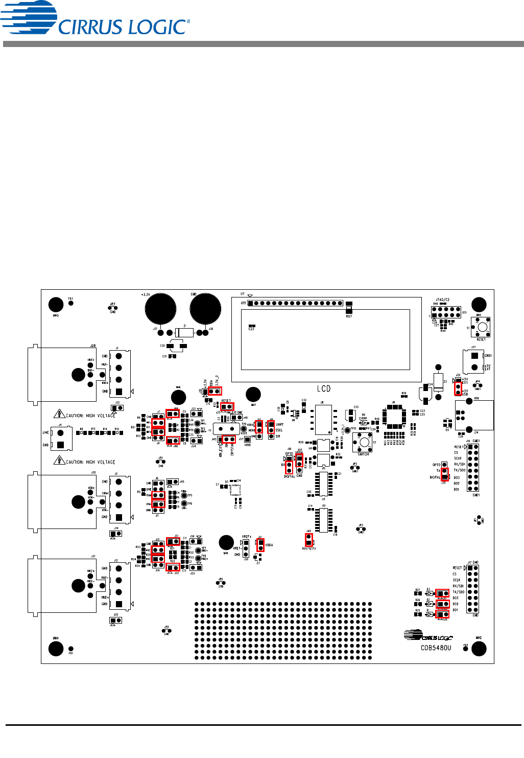
1.2 Evaluation Board Overview
The board is partitioned into two main sections: analog and digital. The analog section consists of the
CS5480, passive anti-aliasing filters, and a high-voltage section with attenuation resistor networks. The
digital section consists of the C8051F342 microcontroller, LCD, the test switches, the reset circuitry, and
the USB interface. The board also has a user-friendly power supply connection. The assembly information
and default configurations for jumpers are shown below.
Figure 1. CDB5480U Assembly Drawing & Default Configuration