
User Manual


Table Of Contents
- Features
- Table of Contents
- List of Figures
- 1. Hardware
- 2. Software
- 2.1 Installation Procedure
- 2.2 Using the Software
- 2.3 Start-up Window
- 2.4 Connect Menu
- 2.5 System Menu
- 2.5.1 Setup Window
- 2.5.1.1 Refresh Screen Button
- 2.5.1.2 Reset DUT Button
- 2.5.1.3 Save Config and Load Config Buttons
- 2.5.1.4 CS5480 MCLK Frequency
- 2.5.1.5 Configuration Registers
- 2.5.1.6 Pulse Control Register
- 2.5.1.7 Pulse Width and Pulse Rate Registers
- 2.5.1.8 Phase Compensation
- 2.5.1.9 Integrator Gain, System Gain
- 2.5.1.10 Sample Count, Cycle Count, Settle Time
- 2.5.1.11 Epsilon
- 2.5.1.12 ZXNUM
- 2.5.1.13 Mask Register
- 2.5.1.14 Temperature Registers
- 2.5.1.15 Zero-crossing Level and No Load Threshold
- 2.5.1.16 V1/V2 Sag, V1/ V2 Swell, and I1/I2 Overcurrent Registers
- 2.5.1.17 Channel Selection Level, Channel Select Minimum Amplitude, and Voltage Fixed RMS Reference Registers
- 2.5.1.18 Register Checksum, SerialCtrl Registers
- 2.5.1 Setup Window
- 2.6 Calibration Window
- 2.7 Conversion Window
- 2.8 Cirrus Test Window
- 2.8.1 Data Collection Window
- 2.8.1.1 Time Domain / FFT/ Histogram Selector
- 2.8.1.2 Config Button
- 2.8.1.3 Collect Button
- 2.8.1.4 Output Button
- 2.8.1.5 Zoom Button
- 2.8.1.6 Channel Select Button
- 2.8.1.7 Output Button & Window
- 2.8.1.8 Configuration Window
- 2.8.1.9 Collecting Data Sets
- 2.8.1.10 Analyzing Data
- 2.8.1.11 Histogram Information
- 2.8.1.12 Frequency Domain Information
- 2.8.1.13 Time Domain Information
- 2.8.2 Data Collection to File Window
- 2.8.3 Setup and Test Window
- 2.8.1 Data Collection Window
- Appendix A. Bill Of Materials
- Appendix B. Schematics
- Appendix C. Layer Plots
CDB5480U
14 DS893DB5
1.7 Standalone Meter Application
The CDB5480U evaluation board provides a standalone power meter using the CS5480, MCU, and LCD.
The user can enable the power meter by connecting the sensors to the analog inputs, providing power to
the board, and resetting the MCU by pressing the RESET switch. Refer to “Typical Sensor Connections”
on page 11 for details on the sensor connections and “Power Supply Selection” on page 10 the details on
supply options.
The user should not use the GUI to connect the CDB5480U board. If the GUI is connected to the
CDB5480U board the standalone power meter function is disabled and the LCD on the CDB5480U will
read "Cirrus Logic CS5480 Eval GUI". To re-enable the standalone power meter feature, close the GUI
software. The standalone power meter feature will initially show the voltage channels’ RMS register
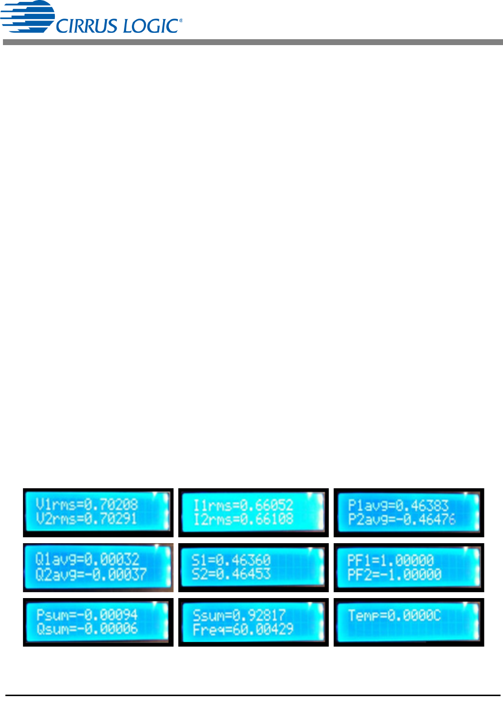
values:
V1rms = N.NNNNN and V2rms = N.NNNNN.
By clicking the onboard switch S2, the standalone power meter will display the following measurement
results:
1. RMS Voltage
2. RMS Current
3. Average Active Power
4. Average Reactive Power
5. Average Apparent Power
6. Power Factors
7. Total Active Power
8. Total Reactive Power
9. Total Apparent Power
10. Fundamental Frequency
11. CS5480 die Temperature
Figure 9. Standalone Power Meter Measurements