
User Manual


Table Of Contents
- Features
- Table of Contents
- List of Figures
- 1. Hardware
- 2. Software
- 2.1 Installation Procedure
- 2.2 Using the Software
- 2.3 Start-up Window
- 2.4 Connect Menu
- 2.5 System Menu
- 2.5.1 Setup Window
- 2.5.1.1 Refresh Screen Button
- 2.5.1.2 Reset DUT Button
- 2.5.1.3 Save Config and Load Config Buttons
- 2.5.1.4 CS5480 MCLK Frequency
- 2.5.1.5 Configuration Registers
- 2.5.1.6 Pulse Control Register
- 2.5.1.7 Pulse Width and Pulse Rate Registers
- 2.5.1.8 Phase Compensation
- 2.5.1.9 Integrator Gain, System Gain
- 2.5.1.10 Sample Count, Cycle Count, Settle Time
- 2.5.1.11 Epsilon
- 2.5.1.12 ZXNUM
- 2.5.1.13 Mask Register
- 2.5.1.14 Temperature Registers
- 2.5.1.15 Zero-crossing Level and No Load Threshold
- 2.5.1.16 V1/V2 Sag, V1/ V2 Swell, and I1/I2 Overcurrent Registers
- 2.5.1.17 Channel Selection Level, Channel Select Minimum Amplitude, and Voltage Fixed RMS Reference Registers
- 2.5.1.18 Register Checksum, SerialCtrl Registers
- 2.5.1 Setup Window
- 2.6 Calibration Window
- 2.7 Conversion Window
- 2.8 Cirrus Test Window
- 2.8.1 Data Collection Window
- 2.8.1.1 Time Domain / FFT/ Histogram Selector
- 2.8.1.2 Config Button
- 2.8.1.3 Collect Button
- 2.8.1.4 Output Button
- 2.8.1.5 Zoom Button
- 2.8.1.6 Channel Select Button
- 2.8.1.7 Output Button & Window
- 2.8.1.8 Configuration Window
- 2.8.1.9 Collecting Data Sets
- 2.8.1.10 Analyzing Data
- 2.8.1.11 Histogram Information
- 2.8.1.12 Frequency Domain Information
- 2.8.1.13 Time Domain Information
- 2.8.2 Data Collection to File Window
- 2.8.3 Setup and Test Window
- 2.8.1 Data Collection Window
- Appendix A. Bill Of Materials
- Appendix B. Schematics
- Appendix C. Layer Plots
CDB5480U
12 DS893DB5
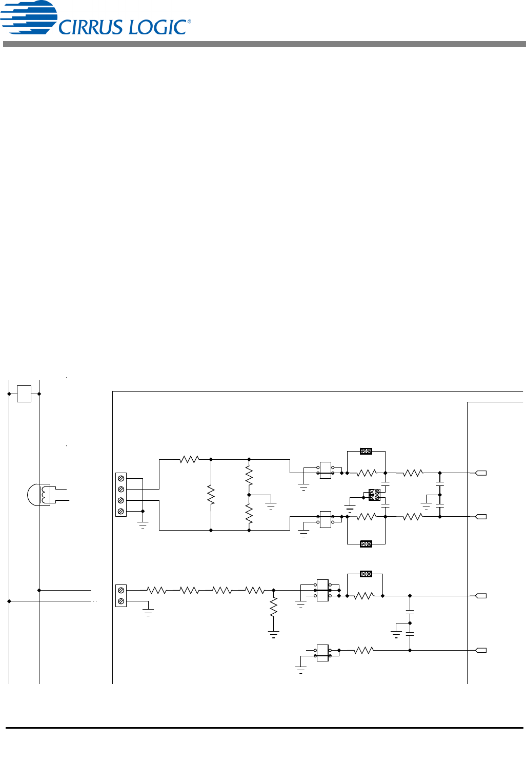
1.6.2 Current Transformer Power Meter Example
A slightly more expensive option is to use a current transformer (CT) to connect the AC current to the
CDB5480U evaluation board. Figure 7 depicts the voltage and current connections for a CT sensor and
its associated filter configurations.
NEVER “open circuit” a CT. Make sure that all signals are well connected before the power source is
turned on. Extreme care should be taken when connecting high-voltage signals to the CDB5480U
evaluation board.
The burden resistor (R11/R22) is necessary in a CT application to convert the secondary current into
voltage. Knowledge of the current transformers turns ratio (N) is key to determining the proper CS5480
input voltage (V
burden
) that the meter places on the system. The optimum secondary voltage (V
burden
) at
the maximum current input should be 10% less than the maximum channel voltage of 250mVp with I-
channel PGA = 10x. The secondary voltage (V
burden
) is determined by converting the primary current to
the secondary current. Then the secondary current (I
burden
) can be converted into a voltage by Ohm's
Law.
The secondary voltage (V
burden
) is sourced to the CS5480 through a simple low-pass, anti-alias filter, and
this voltage should not exceed the 250mVp.
Figure 7. Current Transformer Power Meter
V
burden
I
burden
R
burden
I
primary
N
------------------
R
burden
==
IIN1-/IIN2-
IIN1+/IIN2+
GND
GND
GND
LINE
CS5480
CDB5480U
PHASE
J1/J12
J4
J7/J13
J8/J14
J11
J6
R5
1K
C5/C11
0.033UF
C6/C12
0.033UF
C9
0.027UF
C4
0.027UF
R11/R22
2.2
R1/R21
100
R2/R22
100
R7
1K
R6
1K
R9/R23
1K
R13/R24
1K
R8
422K
R12
422K
R14
422K
R15
422K
R49/R52 1K
R50/R53 1K
C34/C1
0.033UF
C35/C2
0.033UF
J44/J51
J46/J52
R51/R54
0
J45
J53/J56
J54/J55
IIN1+/IIN2+
IIN1-/IIN2-
VIN-
VIN+