
User Manual


Table Of Contents
- Features
- Table of Contents
- List of Figures
- 1. Hardware
- 2. Software
- 2.1 Installation Procedure
- 2.2 Using the Software
- 2.3 Start-up Window
- 2.4 Connect Menu
- 2.5 System Menu
- 2.5.1 Setup Window
- 2.5.1.1 Refresh Screen Button
- 2.5.1.2 Reset DUT Button
- 2.5.1.3 Save Config and Load Config Buttons
- 2.5.1.4 CS5480 MCLK Frequency
- 2.5.1.5 Configuration Registers
- 2.5.1.6 Pulse Control Register
- 2.5.1.7 Pulse Width and Pulse Rate Registers
- 2.5.1.8 Phase Compensation
- 2.5.1.9 Integrator Gain, System Gain
- 2.5.1.10 Sample Count, Cycle Count, Settle Time
- 2.5.1.11 Epsilon
- 2.5.1.12 ZXNUM
- 2.5.1.13 Mask Register
- 2.5.1.14 Temperature Registers
- 2.5.1.15 Zero-crossing Level and No Load Threshold
- 2.5.1.16 V1/V2 Sag, V1/ V2 Swell, and I1/I2 Overcurrent Registers
- 2.5.1.17 Channel Selection Level, Channel Select Minimum Amplitude, and Voltage Fixed RMS Reference Registers
- 2.5.1.18 Register Checksum, SerialCtrl Registers
- 2.5.1 Setup Window
- 2.6 Calibration Window
- 2.7 Conversion Window
- 2.8 Cirrus Test Window
- 2.8.1 Data Collection Window
- 2.8.1.1 Time Domain / FFT/ Histogram Selector
- 2.8.1.2 Config Button
- 2.8.1.3 Collect Button
- 2.8.1.4 Output Button
- 2.8.1.5 Zoom Button
- 2.8.1.6 Channel Select Button
- 2.8.1.7 Output Button & Window
- 2.8.1.8 Configuration Window
- 2.8.1.9 Collecting Data Sets
- 2.8.1.10 Analyzing Data
- 2.8.1.11 Histogram Information
- 2.8.1.12 Frequency Domain Information
- 2.8.1.13 Time Domain Information
- 2.8.2 Data Collection to File Window
- 2.8.3 Setup and Test Window
- 2.8.1 Data Collection Window
- Appendix A. Bill Of Materials
- Appendix B. Schematics
- Appendix C. Layer Plots
CDB5480U
DS893DB5 11
1.6 Typical Sensor Connections
The CDB5480U evaluation board provides connections directly to several types of sensors. Flexible
onboard filter networks provide a convenient configuration for three common transducers, including
current shunt, current transformer (CT), or Rogowski coil.
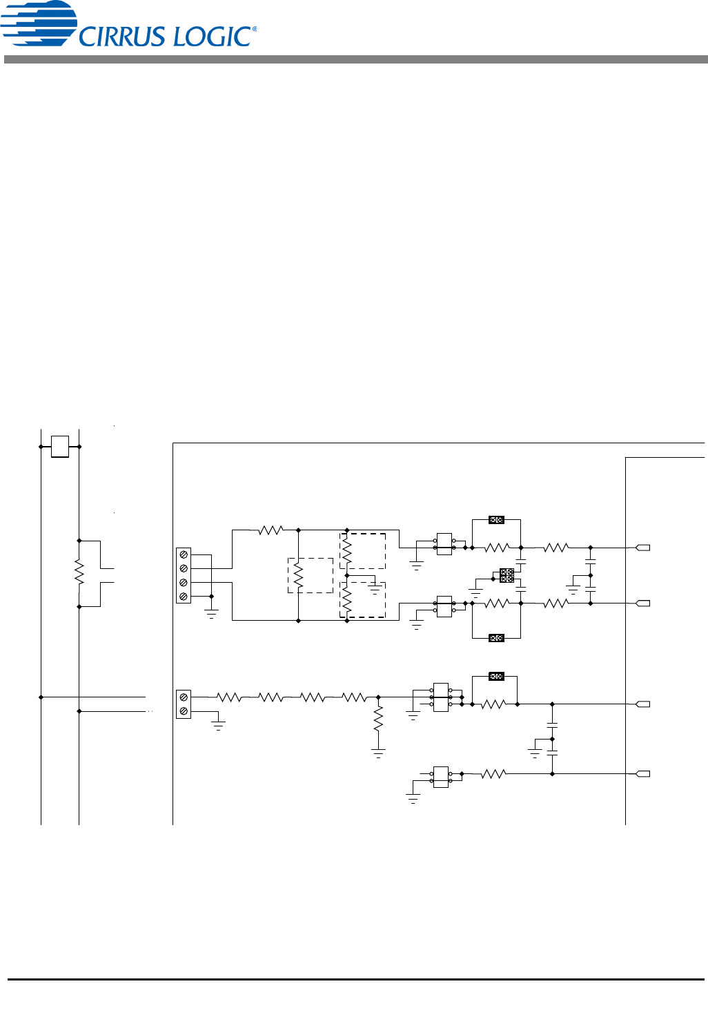
1.6.1 Shunt Power Meter Example
A low-cost current shunt configuration is easily achievable with the CDB5480U evaluation board.
Figure 6 depicts the voltage and current connections for a shunt sensor and its associated filter
configurations.
It is strongly recommended that a low-side (neutral path) current shunt is used — especially in high-
voltage situations. Make sure that all signals are well connected before the power source is turned on.
Extreme care should be taken when connecting high-voltage signals to the CDB5480U evaluation board.
In this configuration it is unnecessary to use a burden resistor. A single anti-alias filter is all that is required
for the current channel. Below the filter corner frequency, the CS5480 inputs will see the same voltage
that is across the shunt. Therefore, the shunt voltage should be kept below the maximum of 50mVp with
I-Channel PGA = 50x. A 10% margin is recommended for the shunt voltage (45mVp).
Figure 6. Shunt Sensor Power Meter
IIN1-/IIN2-
IIN1+/IIN2+
GND
GND
GND
LINE
CS5480
CDB5480U
PHASE
NEUTRAL
J1/J12
J4
J7/J13
J8/J14
J11
J6
R5
1K
C5/C11
0.033UF
C6/C12
0.033UF
C9
0.027UF
C4
0.027UF
R11/R22
NO POP
R1/R21
100
R2/R22
100
R7
1K
R6
1K
R9/R23
NO POP
R13/R24
NO POP
R8
422K
R12
422K
R14
422K
R15
422K
R49/R52 1K
R50/R53 1K
C34/C1
0.033UF
C35/C2
0.033UF
J44/J51
J46/J52
R51/R54
0
J45
J53/J56
J54/J55
SHUNT
IIN1+/IIN2+
IIN1-/IIN2-
VIN-
VIN+