
Instruction Manual


8 DS963DB1
CDB53L30
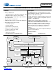
3 System Connections and Jumper Settings
J34 CONTROL
SHORTS
Gang control signals of
CS53L30 #1 and
CS53L30 #2
Shunted
Open
1
Control signals are tied.
Control signals are independent.
J39, J44, J45, J86,
J73, J78, J51, J46
Rbias
SHORT
Shunt across the
1.8 k bias resistor
Shunted
Open
1
1.8-k bias resistor is shunted (for three-wire mic connection).
1.8-k bias resistor is not shunted (for two-wire mic connection).
J38, J43, J42, J85,
J72, J77, J50, J41
Bias to AIN+ Connect mic bias to
noninverting input
Shunted
Open
1
Mic bias tied to AIN+.
Mic bias not tied to AIN+.
J36, J3, J15, J18,
J10, J21, J24, J27
IN– to GND Connect inverting input
to ground
Shunted
Open
1
IN– tied to ground (for pseudodifferential input).
IN– not tied to ground (for true differential input).
J36, J3, J15, J18,
J10, J21, J24, J27
SLEEVE to
GND
Connect TRS sleeve
conductor to ground
Shunted
1
Open
Sleeve tied to ground.
Sleeve floating.
J37 SYNC
DIRECTION
Configure direction of
synchronization signal
SYNC IN
SYNC OUT
1
Sync signal is input (from another CDB53L30).
Sync signal is output (to another CDB53L30).
J1 VA I-SENSE CS53L30 VA current
measurement
Shunted
1
Open
1- current measurement resistor is shorted.
1- current measurement resistor is in series with CS53L30 VA,
allowing direct measurement of VA supply current at J1.
J8 VP
I-SENSE
CS53L30 VP current
measurement
Shunted
1
Open
1- current measurement resistor is shorted.
1- current measurement resistor is in series with CS53L30 VP,
allowing direct measurement of VP supply current at J8.
1.Indicates default factory settings.
Table 3-3. LED Indicators
LED Indication Status Function
D4 USB present On
Off
Indicates there is a USB connection to the CDB53L30.
Indicates there is not a USB connection to the CDB53L30.
Table 3-2. CDB53L30 Jumper Settings (Cont.)
Jumper Pin Block Connection Purpose Position Function Selected