
Instruction Manual


6 DS963DB1
CDB53L30
2 Quick-Start Guide
2 Quick-Start Guide
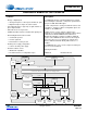
This section describes a basic setup procedure for the CDB53L30. After completing the steps in Fig. 2-1, the CDB53L30
will be configured to accept eight single-ended or differential analog line inputs and will output four two-channel I
2
S
streams at a sample rate of 48 kHz.
Figure 2-1. CDB53L30 Factory Default Jumper Settings
Table 2-1. Quick-Start Serial Header Signal Descriptions
Header Pin Direction Frequency Description
MCLK IN N/A N/A Not used
MCLK OUT Output 12.288 MHz Master clock
SCLK Output 3.072 MHz I
2
S bit clock
LRCK/FSYNC Output 48 kHz I
2
S left/right clock
1.ASP1_SDOUT Output N/A ASP1_SDOUT I
2
S data from CS53L30 #1;
Left channel corresponds to 1.AIN1, right channel corresponds to 1.AIN2
6
1 2
3
4
5
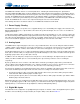
Return all jumpers to the
default factory settings. See
Table 3-2 and Figure 3-1.
Install the FlexGUI
software. See Section 4.1.
Connect a +5 V power
supply to the +5V_EXT
and GND binding posts .
Connect a USB cable
from a Windows-
compatible PC .
Start the FlexGUI software. Using
the “Quick-Setup” drop -down list on
the “Board Config” tab , restore the
factory register configuration called
“2. Analog in – I2S – 48k FS –
12.288M MCLK – Master mode” .
7
Connect differential or single -
ended signals to any of the
eight 1/8" input jacks. Full-
scale input corresponds to a
differential voltage of 1.48 Vpp.
When using a single -ended
source, shunt IN
–
to ground by
placing a jumper at the “IN
–
“
position (Pins 1 and 2) on the
Sleeve/IN- jumper pin block .
8
Connect a serial audio
analyzer to the Serial
Header . The header
signals are described
in Table 2-1.
9
Optional : Connect
an audio analyzer to
the S/PDIF RCA or
optical output . The
stereo pair at these
outputs corresponds
to analog input pair
1.AIN1 and 1.AIN2.
Return all jumpers to default
factory settings. See
Table 3-2 and Fig. 3-1.
Install the FlexGUI software.
See Section 4.1.
Connect a serial audio
analyzer to the Serial
Header. The header
signals are described
inTable 2-1.