
Instruction Manual


20 DS963DB1
CDB53L30
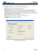
5 Performance Plots
Figure 5-17. THD+N (Relative) vs. Frequency,
Preamp Setting: 0 dB, –1 dBFS
Figure 5-18. THD+N (Relative) vs. Frequency,
Preamp Setting: +10 dB, –1 dBFS
Figure 5-19. THD+N (Relative) vs. Frequency,
Preamp Setting: +20 dB, –1 dBFS
Figure 5-20. THD+N (Relative) vs. Level, Preamp Setting: 0 dB,
PGA Setting: 0 dB, 1 kHz
Figure 5-21. THD+N (Relative) vs. Level, Preamp Setting: 0 dB,
PGA Setting: +12 dB, 1 kHz
Figure 5-22. THD+N (Relative) vs. Level,
Preamp Setting: +10 dB, PGA Setting: 0 dB, 1 kHz
G
%
N N N N N
+]
PGA Setting: +12 dB
PGA Setting: 0 dB
Note: The low-frequency distortion
is dominated by the MLCC Class II
DC blocking capacitor (0.1 F). To
reduce this distortion, reduce the
corner frequency by selecting a
larger cap, or choose a different cap
type such as film or MLCC Class I.
G
%
N N N N N
+]
PGA Setting: 0 dB
PGA Setting: +12 dB
G
%
N N N N N
+]
PGA Setting: +12 dB
PGA Setting: 0 dB
G
%
G%U
G
%
G%U
G
%
G%U