
Instruction Manual


12 DS963DB1
CDB53L30
4.3 Using the FlexGUI Tabs
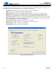
4.3.1 Board Config Tab
The “Board Config” tab contains the controls for configuring the MCLK source, S/PDIF transmitter, serial header, and
CS53L30 mute signals. The individual functions of this tab are described below.
• Quick Setup—Drop-down box for selecting a factory preset register configuration.
• MCLK—Settings for onboard MCLK frequency and MCLK routing.
• S/PDIF Transmitter—Settings for the CS8406 S/PDIF transmitter. See Section 1.5 for more information.
• Mute Control—Configures the state of the microcontroller I/O pins which drive the CS53L30 MUTE inputs. To
enable these controls, jumper pin block J4 must have the corresponding “FlexGUI CNTL” jumpers placed.
• Serial Header Direction—Configures the SCLK and LRCK/FSYNC signal direction for the serial audio header, J29.
When configured as Master, SCLK and LRCK/FSYNC are outputs from the CDB53L30. When configured as Slave,
SCLK and LRCK/FSYNC are inputs to the CDB53L30.
• Device and Revision I.D.—Displays the CS53L30 revision information.
• Refresh—Reads all registers in all devices and updates the values in the FlexGUI.
• Reset CS53L30-1—Sends a reset pulse to CS53L30 #1.
• Reset CS53L30-2—Sends a reset pulse to CS53L30 #2.
Figure 4-4. The “Board Config” Tab