
User Manual


4
4.2.2.4 DAI Input of CS485xx
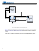
Each of the Audio In Elements listed above are connected to a DAI element. This represent the DAI port of the
DSP. As shown in Fig. 4-5. This dialog allows the user to set the following parameters for the CS485xx:
• SCLK Polarity
• LRCLK Polarity
• Reference Clock - Set to the frequency of the crystal driving the CS485XX(Y1). This is the reference clock
is used to determine the clock dividers needed to derive Fs in ADC-only applications. If this number
changes, then all dividers for LRCLK/SCLK will change by the same ratio (e.g., @24.576 MHz MCLK/512
= 1Fs = LRCLK, @12.288 MHz MCLK/256 = 1Fs = LRCLK.
.
Figure 4-5. DAI Device Properties
4.2.3 Changing Audio Output Configuration
The audio output section of the CDB48500 is configured through the “Audio Out” block in DSP Composer.
4.2.3.1 DAO Output of CS485xx
The digital audio output (DAO) of the CS485XX is very flexible, making it compatible with a wide variety of audio
devices. This port can configured using the dialog box shown in Fig. 4-6. Right-click on the “Audio Out” block,
then select Device Properties. Right-clicking the “DAO” block and selecting Device Properties produces the
DAO Properties dialog.