
Instruction Manual


CDB1610A-8W
12 DS1011DB3
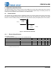
6. INDUCTOR CONSTRUCTION
The CDB1610A-8W includes a critical conduction mode (CRM) boost converter that provides power factor correction
and dimmer compatibility with a constant output current, quasi-resonant flyback stage. The following sections de-
scribe the boost and flyback inductors installed on the CDB1610A-8W.
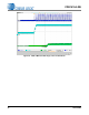
6.1 Boost Inductor
The CS1610A uses an adaptive dimmer compatibility algorithm to control the boost inductor stage, which guaran-
tees dimmer compatibility operation plus enables flicker-free operation with leading-edge, trailing-edge, and digital
dimmers. The boost auxiliary winding is used for zero-current detection (ZCD) and supplies power to the CS1610A.
Figure 7. Boost Inductor Schematic
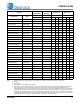
6.1.1 Electrical Specifications
Characteristics conditions:
• Operating temperature range: -25 °C to +120 °C (including coil heat)
Notes: 1. Measured across pins 1 and 2
2. Measured across pins 5 and 4
Parameter Condition Symbol Min Typ Max Unit
Boost Inductor
Primary Inductance (Note 1)
f
resonant
=10kHz, 0.3V at 20°C
L
P
1.305 1.45 1.595 mH
Primary DC Resistance (Note 1)
t
DCR
=20°C
3.28 4.1 4.92
Auxiliary DC Resistance (Note 2)
t
DCR
=20°C
0.456 0.57 0.684
2
1
5
4
400T
#37AWG
(0.12mm)
22T
#37 AWG
(0.12 mm)
Primary
Auxillary