
User guide


AN312REV2 7
AN312
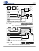
Figure 11. Clock Circuit as Used by Mode 0x01 with CM-2 and Semiconductors
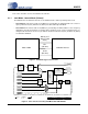
3.1.4 0x04 Mode - External Master Clock
In External Master Clock Mode, all clocks are derived from an externally supplied master clock of
24.576 MHz. This mode is provided because it is easy to accomplish using the existing clock circuitry. It
is most useful when trying to synchronize one or more CobraNet devices to a distributed Master Clock.
However, it has little practical utility because it is difficult to properly distribute a clock of this frequency
and does not provide a means to ensure synchronization of the audio clocks (SCLK, FS1). Note that
MCLK_OUT is not a copy of MCLK_IN. MCLK_OUT is derived from the VCXO, which is not controlled in
this mode and is not synchronous with the supplied MCLK_IN. When operating in this mode:
• As Conductor: MCLK is sourced directly from MCLK_IN. FS1 and SCLK are derived from MCLK_IN.
• As Performer: MCLK is sourced directly from MCLK_IN. FS1 and SCLK are derived from MCLK_IN.
Figure 12. 0x04 Mode Typical Connection (Synchronization to an Externally-Supplied Master Clock)
Beat Received
VCXO
24.576MHz
+/- 100 PPM
DAC
MCLK_IN
MCLK_SEL
REFCLK
MCLK
MUX
Beat
MUX
Phase
Detector
Sample
Phase
Counter
Loop
Filter
control
Clock
Out
MCLK_OUT (master)
FS1 (word)
SCK (bit)
Audio
Clock
Generator
Clock Config
Signal
Path
Control
Path
External
Hardware
CobraNet
Processor
Software
Active
Signal
Pth
CobraNet Interface
FS1
(LR clock)
SCLK
(Bit clock)
MCLK_IN24.576 MHz