
Specifications
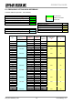
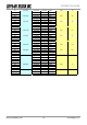

OG_STD-302N-R_v15e Circuit Design, Inc.
17
OPERATION GUIDE
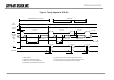
Measurement is done with the PLL setting control
board prepared by Circuit Design.
Purple line shows typical value.
Yellow and black line shows maximum and
minimum of the specification.
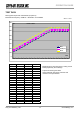
TEST DATA
RSSI typical output level characteristic (Purple line)
Measurement frequency: 434MHz / Modulation: unmodulated
25°C +/- 5°C
RSSI vs dBm
0
100
200
300
400
500
600
700
800
-120 -115 -110 -105 -100 -95 -90 -85 -80 -75 -70 -65 -60 -55 -50 -45 -40 -35 -30 -25 -20
dBm
mV
MIN
RSSI(mV)
MAX
Sig (dBm) MIN RSSI (mV) MAX
-120 134 184 234
-115 168 218 268
-110 202 252 302
-105 238 288 338
-100 270 320 370
-95 306 356 406
-90 346 396 446
-85 380 430 480
-80 410 460 510
-75 444 494 544
-70 482 532 582
-65 516 566 616
-60 558 608 658
-55 586 636 686
-50 596 646 696
-45 596 646 696
-40 598 648 698
-35 600 650 700
-30 600 650 700
-25 600 650 700
-20 600 650 700