
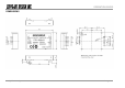
Specifications

.
OG_STD-302N-R_v15e Circuit Design, Inc.
10
OPERATION GUIDE
PLL IC CONTROL
PLL IC control
OSCin
OSCout
Vp
VCC
Do
GND
Xf in
Fin
R
P
STD-302
Control pin name
ZC
PS
LE
Data
2kohm
MB15E03SL
Reference Oscillator
LPF
Voltage Controled
Oscillator
VCO
PLL
CLK
DATA
LE
LD
LD/f out
+2.8v
#:Control v oltage = +2.8v
21.25MHz
up to 1200MHz
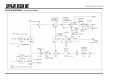
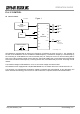
Figure 1
CLK
2kohm
2kohm
2kohm
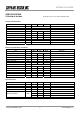
STD-302N-R is equipped with an internal PLL frequency synthesizer as shown in Figure 1. The operation of
the PLL circuit enables the VCO to oscillate at a stable frequency. Transmission frequency is set externally by
the controlling IC. STD-302N-R has control terminals (CLK, LE, DATA) for the PLL IC and the setting data is
sent to the internal register serially via the data line. Also STD-302N-R has a Lock Detect (LD) terminal that
shows the lock status of the frequency. These signal lines are connected directly to the PLL IC through a 2 kΩ
resistor.
The interface voltage of STD-302N-R is 2.8 V, so the control voltage must be the same.
STD-302N-R comes equipped with a Fujitsu MB15E03SL PLL IC. Please refer to the manual of the PLL IC.
The following is a supplementary description related to operation with STD-302N-R. In this description, the
same names and terminology as in the PLL IC manual are used, so please read the manual beforehand.