
User's Manual

35
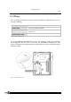
Installing 5000/5100:
Wiring
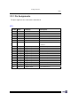
2.2.4 Digital Inputs/Outputs
DI/DO are four sets of separate signal on the terminals.
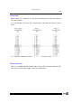
DI via JP3
D/I type: A photo-coupler that can be used to monitor external devices.
For example, a button can be used to activate and open a door.
DI wiring allows four groups of signals and is done through JP3.
DI Group No. Pin No. (+) Pin No. (–) Pin No. (+5V) Pin No. (GND)
DIN1 (Default) 2 3 1 17 or 12
DIN2 4 5 1 17 or 12
DIN3 6 7 1 17 or 12
DIN4 8 9 1 17 or 12
Table 12: D/I groups
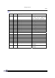
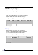
DO via JP2
D/O type: A relay that can be used to control external devices.
For example, an alarm can be activated for alerting abnormal status.
Or, a door lock switch to lock the door for a certain condition.
DO wiring allows four groups of signals and is done through JP2.
DO Group No. Pin No.
(Normal Open)
Pin No. (Common) Pin No.
(Normal Close)
DO1 (Default) 17 18 19
DO2 14 15 16
DO3 11 12 13
DO4 8 9 10
Table 13: D/O groups