
User's Manual
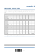
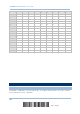
Table Of Contents
- 英文-2564MR Scanner User Guide_v1.00-FOR FCC IC-20170217
- Important Notices
- Release Notes
- Introduction
- Quick Start
- Understanding the Barcode Scanner
- 1.1 Battery
- 1.2 Memory
- 1.3 LED Indicator
- 1.4 Beeper
- 1.5 Send “NR” to Host
- 1.6 Scan Modes
- 1.7 Scanning Timeout
- 1.8 Delay between Re-read
- 1.9 Read Redundancy (1D)
- 1.10 Addon Security for UPC/EAN Barcodes
- 1.11 Auto-Sense Mode
- 1.12 Negative Barcodes
- 1.13 Picklist Mode
- 1.14 Mobile Phone/Display Mode
- 1.15 Illumination Brightness
- 1.16 Serial Number Stamp
- 1.17 2D Decode Setting
- Selecting Output Interface
- 2.1 BT HID
- 2.1.1 Activate BT HID & Select Keyboard Type
- 2.1.2 Reset Connection
- 2.1.3 Keyboard Settings
- 2.1.4 Inter-Character Delay
- 2.1.5 Inter-Function Delay
- 2.1.6 HID Character Transmit Mode
- 2.1.7 Special Keyboard Feature
- 2.1.8 Keypad Support for iPhone/iPad
- 2.1.9 Transmit Speed
- 2.1.10 Simple Pairing for iPhone/iPad
- 2.1.11 BT HID Slave/Master Switching
- 2.1.12 BT HID Auto-Reconnection
- 2.2 BT SPP Slave
- 2.3 BT SPP Master
- 2.4 Keyboard Wedge via BT Cradle
- 2.5 RS-232 via BT Cradle
- 2.6 USB HID via BT Cradle
- 2.7 USB Virtual COM via BT Cradle
- 2.1 BT HID
- Setting up a WPAN Connection
- Changing Symbology Settings
- 4.1 Codabar
- 4.2 Code 25 – Industrial 25
- 4.3 Code 25 – Interleaved 25
- 4.4 Code 25 – Matrix 25
- 4.5 Code 25 – Chinese 25
- 4.6 Italian Pharmacode (Code 32)
- 4.7 Code 39
- 4.8 Trioptic Code 39
- 4.9 Code 93
- 4.10 Code 128
- 4.11 GS1-128 (EAN-128)
- 4.12 ISBT 128
- 4.13 GS1 DataBar (RSS Family)
- 4.14 MSI
- 4.15 EAN-8
- 4.16 EAN-13
- 4.17 UCC Coupon Extended Code
- 4.18 UPC-A
- 4.19 UPC-E
- 4.20 Code 11
- 4.21 Composite Code
- 4.22 US Postal Code
- 4.23 UK Postal Code
- 4.24 More Postal Code
- 4.25 2D Symbologies
- 4.26 Macro PDF
- Defining Output Format
- Applying Formats for Data Editing
- Specifications
- Firmware Upgrade
- Host Serial Commands
- Keyboard Wedge Table
- Numeral Systems
- Reading Driver Licenses

2564MR Barcode Scanner User Guide
1) Connect the interface cable, RS-232 or USB, between the cradle and your computer.
For USB Virtual COM, you may need to install its driver first!
2) Connect the power supply cord from the cradle to a proper power outlet.
The Communication LED will indicate when the cradle can accept serial commands after
initializing. Refer to the table below.
If the output interface is USB Virtual COM or RS-232, run HyperTerminal.exe on your
computer. While the Communication LED on the cradle is purple (red with flashing
blue), type the serial command within three seconds.
If the output interface is USB HID, press the “Num Lock” or “Caps Lock” key on your
keyboard 5 times within 3 seconds while the Communication LED on the cradle is
flashing red and blue. This will change the interface from USB HID to USB Virtual
COM and the Communication LED will become purple (red with flashing blue). Then,
run HyperTerminal.exe on your computer. While the Communication LED on the
cradle is purple (red with flashing blue), type the serial command within three
seconds. After configuring via serial commands, the interface will be reset to USB
HID after re-connecting the power supply cord.
Communication LED Meaning
--- Blue,
solid
Initialize
Red,
solid
Blue,
flashing
Serial command mode with USB Virtual COM or RS-232: wait 3 seconds for
starting a serial command
Red,
flashing
Blue,
flashing
Serial command mode with USB HID changed to USB Virtual COM first: wait 3
seconds for pressing [Num Lock] or [Caps Lock] 5 times via keyboard
258
Enter Setup