
User's Manual
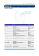
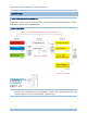
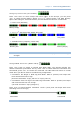
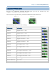

Table Of Contents
- IMPORTANT NOTICES
- RELEASE NOTES
- INTRODUCTION
- QUICK START
- UNDERSTANDING RFID READER
- COMMUNICATION INTERFACE
- SETTING UP A WPAN CONNECTION
- SCANNING UHF RFID TAG
- DEFINING OUTPUT FORMAT
- ALTERNATE MODE
- SPECIFICATIONS
- FIRMWARE UPGRADE
- ASCII TABLE
- SCAN CODE
- STATUS CODE

37
Chapter 1
Understandin
g
RFID Reader
1.4 LED INDICATORS
The five LEDs on the RFID Reader are used to provide a feedback to users about the
behavior of the RFID Reader. For example, the LED1 becomes solid red and goes off
upon powering on.
The status of LED indicators may vary depending on working modes ─ General, Function
Key and Bluetooth
®
Pairing Modes.
1.4.1 GENERAL MODE
In General mode LEDs show you normal system status without any advanced
configuration.
LED
Color Status Description
Red On-Off Power on, with one long beeps (high tone,
LED1 on for 1 second and then off.)
Red On
Charging Fail
Power Off (With F1+F2 pressed to
power off, it remains solid red until both
of the function keys are released)
Red Flashing Charging (On/Off ratio 0.5s:0.5s)
LED1-Power
Green Flashing Charging Done (On/Off ratio 0.5s:0.5s)
On/Off ratio 0.5s:0.5s indicates the RFID
Reader is waiting for connection
On/Off ratio 0.1s:0.1s indicates the RFID
Reader receives a PIN code request from
host (flashing more quickly than waiting
connection)
LED2-Bluetooth
®
Communication
Blue Flashing
On/Off ratio 0.02s:3s indicates the RFID
Reader has established a Bluetooth
®
connection successfully.
LED3-RFID Tag Access
Green On-Off Good Read/Write with one short beeps (high
tone). The pitch and duration are
programmable.
LED4-Data
Transmission
Green Flashing Indicate the data is transmitted between
RFID Reader and host. The speed of
flashing varies with data rate.
Green Flashing Flashing ((On/Off ratio 0.02s:3s) indicates
Free memory size > 10%
** Only for memory mode
LED5-Memory Status
Red Flashing Flashing (On/Off ratio 0.02s:3s) indicates
memory under 10%
** Only for memory mode