
User Manual
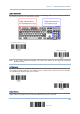
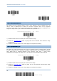
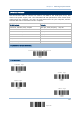
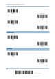

Table Of Contents
- IMPORTANT NOTICES
- RELEASE NOTES
- INTRODUCTION
- QUICK START
- UNDERSTANDING THE BARCODE SCANNER
- SELECTING OUTPUT INTERFACE
- SETTING UP A WPAN CONNECTION
- CHANGING SYMBOLOGY SETTINGS
- 4.1 CODABAR
- 4.2 CODE 25 – INDUSTRIAL 25
- 4.3 CODE 25 – INTERLEAVED 25
- 4.4 CODE 25 – MATRIX 25
- 4.5 CODE 39
- 4.6 CODE 93
- 4.7 CODE 128
- 4.8 EAN-8
- 4.9 EAN-13
- 4.10 GS1-128 (EAN-128)
- 4.11 ISBT 128
- 4.12 MSI
- 4.13 FRENCH PHARMACODE
- 4.14 ITALIAN PHARMACODE
- 4.15 PLESSEY
- 4.16 GS1 DATABAR (RSS FAMILY)
- 4.17 TELEPEN
- 4.18 UPC-A
- 4.19 UPC-E
- DEFINING OUTPUT FORMAT
- APPLYING FORMATS FOR DATA EDITING
- SPECIFICATIONS
- Appendix I - FIRMWARE UPGRADE
- Appendix II - HOST SERIAL COMMANDS
- Appendix III - KEYBOARD WEDGE TABLE
- Appendix IV - NUMERAL SYSTEMS

63
Update
Chapter 2
Selecting Output Interface
2.4.5 STOP BIT
2.4.6 FLOW CONTROL
By default, there is no flow control in use. Select the flow control (handshake) method.
Options
Description
No No flow control
Scanner Ready The scanner will activate the RTS signal upon powering on. After each good
read, the scanner will then wait for the CTS signal to become active. Data
will not be sent until the CTS signal becomes active.
Data Ready
T
he RTS signal will be activated after each good read. The scanner will then
wait for the CTS signal to become active. Data will not be sent until the CTS
signal becomes active.
Inverted Data Ready It works the same as the Data Ready flow control, except that the RTS
signal level is inverted.
Odd
2 stop bits
*
1 stop bit
*None
S
canner Ready