
User Manual

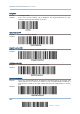

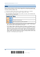
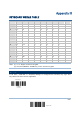
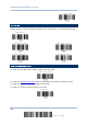
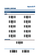
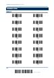
Table Of Contents
- IMPORTANT NOTICES
- RELEASE NOTES
- INTRODUCTION
- QUICK START
- UNDERSTANDING THE BARCODE SCANNER
- SELECTING OUTPUT INTERFACE
- SETTING UP A WPAN CONNECTION
- CHANGING SYMBOLOGY SETTINGS
- 4.1 CODABAR
- 4.2 CODE 25 – INDUSTRIAL 25
- 4.3 CODE 25 – INTERLEAVED 25
- 4.4 CODE 25 – MATRIX 25
- 4.5 CODE 39
- 4.6 CODE 93
- 4.7 CODE 128
- 4.8 EAN-8
- 4.9 EAN-13
- 4.10 GS1-128 (EAN-128)
- 4.11 ISBT 128
- 4.12 MSI
- 4.13 FRENCH PHARMACODE
- 4.14 ITALIAN PHARMACODE
- 4.15 PLESSEY
- 4.16 GS1 DATABAR (RSS FAMILY)
- 4.17 TELEPEN
- 4.18 UPC-A
- 4.19 UPC-E
- DEFINING OUTPUT FORMAT
- APPLYING FORMATS FOR DATA EDITING
- SPECIFICATIONS
- Appendix I - FIRMWARE UPGRADE
- Appendix II - HOST SERIAL COMMANDS
- Appendix III - KEYBOARD WEDGE TABLE
- Appendix IV - NUMERAL SYSTEMS

181
Update
Appendix II
Host Serial Commands
3656 SERIAL COMMANDS
Normally, you can configure the 3656 stand by having a connected scanner read
3656-related setup labels.
1) Connect the interface cable, RS-232 or USB, between 3656 and your computer.
2) Connect the power supply cord from 3656 to a proper power outlet.
3) Refer to 3.1.1 Connect to 3656
for the target scanner to connect to 3656.
Read the “Set Connection” label first, and then the “Serial Number” label. Both labels
can be located at the back of 3656.
4) Read the following labels in sequence to configure 3656.
For 3656-related setup labels, refer to the Serial Command table below. Note that for
the “Version” and “GetID” labels, you must run HyperTerminal.exe or any text editor
to receive the information.
If the output interface is USB Virtual COM or RS-232, run HyperTerminal.exe on
your computer to receive the information.
If the output interface is USB HID, run any text editor to receive the information.
E
nter Setup
(3656-
r
elated setup labels)
U
pdate