
Specifications
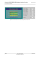
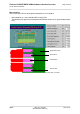
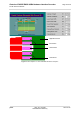
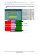
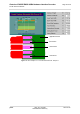
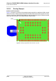
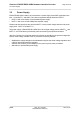
Table Of Contents

Cinterion
®
EHS5-E/EHS5-USR4 Hardware Interface Overview
2.2 RF Antenna Interface
28
ehs5_hio_v04.000 2019-01-16
Confidential / Preliminary
Page 26 of 46
2.2.2.2 Routing Example
Interface to RF Connector
Figure 11 shows the connection of the module‘s antenna pad with an application PCB‘s coaxial
antenna connector. Please note that the EHS5-E/EHS5-USR4 bottom plane appears mirrored,
since it is viewed from EHS5-E/EHS5-USR4 top side. By definition the top of customer's board
shall mate with the bottom of the EHS5-E/EHS5-USR4 module.
Figure 11: Routing to application‘s RF connector - top view
Pad 1