Specifications
Manuals
Brands
CINTERION Manuals
Electronics
EHS5-US
21
22
23
24
25
26
27
28
29
30
Table Of Contents
Contents
Tables
Figures
1 Introduction
1.1 Key Features at a Glance
1.2 EHS5-E/EHS5-USR4 System Overview
2 Interface Characteristics
2.1 Application Interface
2.1.1 USB Interface
2.1.2 Serial Interface ASC0
2.1.3 Serial Interface ASC1
2.1.4 UICC/SIM/USIM Interface
2.1.5 Digital Audio Interface
2.1.6 GPIO Interface
2.1.7 I2C Interface
2.1.8 SPI Interface
2.1.9 PWM Interfaces
2.1.10 Pulse Counter
2.1.11 Status LED
2.1.12 Fast Shutdown
2.2 RF Antenna Interface
2.2.1 Antenna Installation
2.2.2 RF Line Routing Design
2.2.2.1 Line Arrangement Examples
2.2.2.2 Routing Example
2.3 Sample Application
3 Operating Characteristics
3.1 Operating Modes
3.2 Power Supply
4 Mechanics
4.1 Mechanical Dimensions of EHS5-E/EHS5-USR4
5 Regulatory and Type Approval Information
5.1 Directives and Standards
5.2 SAR requirements specific to portable mobiles
5.3 Reference Equipment for Type Approval
5.4 Compliance with FCC and IC Rules and Regulations
6 Document Information
6.1 Revision History
6.2 Related Documents
6.3 Terms and Abbreviations
6.4 Safety Precaution Notes
7 Appendix
7.1 List of Parts and Accessories
Cinterion
®
EHS5-E/EHS5-USR4 Hardware Interface Overview
2.2 RF
Antenn
a Interface
28
ehs5_hio_v04.000
2019-01-16
Confidential / Preliminary
Page 21 of 46
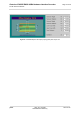
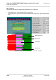
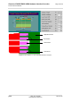
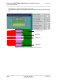
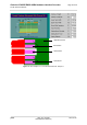
Figure 6:
Embedded Strip
line with 65µm prepreg (1080) and 710µ
m core
1
...
...
19
20
21
22
23
...
...
46