
Specifications
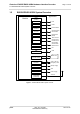
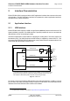
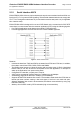
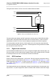
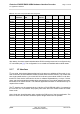
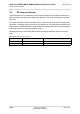
Table Of Contents

Cinterion
®
EHS5-E/EHS5-USR4 Hardware Interface Overview
2.1 Application Interface
28
ehs5_hio_v04.000 2019-01-16
Confidential / Preliminary
Page 17 of 46
After startup, the above mentioned alternative GPIO line assignments can be configured using
AT commands (see [1]). The configuration is non-volatile and available after module restart.
2.1.7 I
2
C Interface
I
2
C is a serial, 8-bit oriented data transfer bus for bit rates up to 400kbps in Fast mode. It con-
sists of two lines, the serial data line I2CDAT and the serial clock line I2CCLK. The module acts
as a single master device, e.g. the clock I2CCLK is driven by the module. I2CDAT is a bi-direc-
tional line. Each device connected to the bus is software addressable by a unique 7-bit ad-
dress, and simple master/slave relationships exist at all times. The module operates as master-
transmitter or as master-receiver. The customer application transmits or receives data only on
request of the module.
The I
2
C interface can be powered via the V180 line of EHS5-E/EHS5-USR4. If connected to
the V180 line, the I
2
C interface will properly shut down when the module enters the Power
Down mode.
Note: Good care should be taken when creating the PCB layout of the host application: The
traces of I2CCLK and I2CDAT should be equal in length and as short as possible.
Table 2: GPIO lines and possible alternative assignment
GPIO Fast
Shutdown
Status
LED
PWM Pulse
Counter
ASC0 ASC1 SPI PCM
GPIO1 DTR0
GPIO2 DCD0
GPIO3 DSR0 SPI_CLK
GPIO4 FST_SHDN
GPIO5 Status LED
GPIO6 PWM2
GPIO7 PWM1
GPIO8 COUNTER
GPIO16 RXD1 MOSI
GPIO17 TXD1 MISO
GPIO18 RTS1
GPIO19 CTS1 SPI_CS
GPIO20 TXDDAI
GPIO21 RXDDAI
GPIO22 TFSDAI
GPIO23 SCLK
GPIO24 RING0