
Specifications
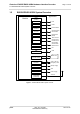
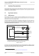
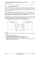
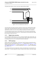
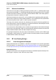
Table Of Contents

Cinterion
®
EHS5-E/EHS5-USR4 Hardware Interface Overview
2 Interface Characteristics
28
ehs5_hio_v04.000 2019-01-16
Confidential / Preliminary
Page 12 of 46
2 Interface Characteristics
EHS5-E/EHS5-USR4 is equipped with an SMT application interface that connects to the exter-
nal application. The SMT application interface incorporates the various application interfaces
as well as the RF antenna interface.
2.1 Application Interface
2.1.1 USB Interface
EHS5-E/EHS5-USR4 supports a USB 2.0 High Speed (480Mbit/s) device interface that is Full
Speed (12Mbit/s) compliant. The USB interface is primarily intended for use as command and
data interface and for downloading firmware.
The external application is responsible for supplying the VUSB_IN line. This line is used for ca-
ble detection only. The USB part (driver and transceiver) is supplied by means of BATT+. This
is because EHS5-E/EHS5-USR4 is designed as a self-powered device compliant with the “Uni-
versal Serial Bus Specification Revision 2.0”
1
.
Figure 2: USB circuit
To properly connect the module's USB interface to the external application, a USB 2.0 compat-
ible connector and cable or hardware design is required. Furthermore, the USB modem driver
distributed with EHS5-E/EHS5-USR4 needs to be installed.
1. The specification is ready for download on http://www.usb.org/developers/docs/
VBUS
DP
DN
VREG (3V075)
BATT+
USB_DP
2)
lin. reg.
GND
Module
Detection only
VUSB_IN
USB part
1)
RING0
Host wakeup
1)
All serial (including R
S
) and pull-up resistors for data lines are implemented.
USB_DN
2)
2)
If the USB interface is operated in High Speed mode (480MHz), it is recommended to take
special care routing the data lines USB_DP and USB_DN. Application layout should in this
case implement a differential impedance of 90Ohm for proper signal integrity.
R
S
R
S
SMT