
Specifications


CINTERION
®
BGS12 Hardware Interface Description
Contents
68 of 109
Page
BGS12 HID_V00.915
Confidential / Released
2019
-
01
-
07
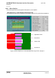
4.2.2 Routing Example
4.2.2.1
Interface to RF Connector
Figure 44 shows the connection of the module‘s antenna pad with an application PCB‘s coaxial
antenna connector. Please note that the BGS12 bottom plane appears mirrored, since it is
viewed from BGS12 top side. By definition the top of customer's board shall mate with the
bottom of the BGS12 module.
Figure 44: Pouting to application‘s RF connector - top view