
Specifications


CINTERION
®
BGS12 Hardware Interface Description
Contents
44 of 109
Page
BGS12 HID_V00.915
Confidential / Released
2019
-
01
-
07
Features:
•
Includes the data lines TXD0 and RXD0, the status lines RTS0 and CTS0 and, in addition,
the modem control lines DTR0, DSR0, DCD0 and RING0.
•
ASC0 is primarily designed for controlling voice calls, GPRS data and for controlling the
GSM module with AT commands.
•
The DTR0 signal will only be polled once per second from the internal firmware of BGS12.
•
The RING0 signal serves to indicate incoming calls and other types of URCs (Unsolicited
Result Code). It can also be used to send pulses to the host application, for example to
wake up the application from power saving state. See [1] for details on how to configure the
RING0 line by AT^SCFG.
•
Configured for 8 data bits, no parity and 1 stop bit.
•
Autobauding supports bit rates from 4,800 bps to 230,400 bps.
•
Supports RTS0/CTS0 hardware flow control.
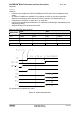
Table 12: DCE-DTE wiring of ASC0
V.24
circuit
DCE DTE
Pad function Signal direction Pad function Signal direction
103 TXD0 Input TXD Output
104 RXD0 Output RXD Input
105 RTS0 Input RTS Output
106 CTS0 Output CTS Input
108/2 DTR0 Input DTR Output
107 DSR0 Output DSR Input
109 DCD0 Output DCD Input
125 RING0 Output RING Input
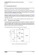
The following figure shows the startup behavior of the asynchronous serial interface ASC0.