
Specifications


CINTERION
®
BGS12 Hardware Interface Description
Contents
42 of 109
Page
BGS12 HID_V00.915
Confidential / Released
2019
-
01
-
07
pliance.
To avoid possible cross-talk from the CCCLK signal to the CCIO signal be careful that both
lines are not placed closely next to each other. A useful approach would be to use a separate
SIM card ground connection to shield the CCIO line from the CCCLK line. A GND line may be
employed for such a case.
Notes: The total capacitors on CCCLK should be less than 12pF. Some device which
connect with CCCLK, have the equivalent capacitors, such as the ESD component and
analogue switch IC. When selecting such component, one should calculate equivalent
capacitors of all device, and make sure they are less than 12pF.
No guarantee can be given, nor any liability accepted, if loss of data is encountered after
removing the SIM card during operation.
Also, no guarantee can be given for properly initialising any SIM card that the user
inserts after having removed a SIM card during operation. In this case, the application
must restart BGS12.
If using a SIM card holder without detecting contact please be sure to switch off the
module before removing the SIM Card or inserting a new one.
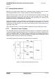
3.7.2 Dual SIM/USIM Card Application
BGS12 can support dual SIM card by add a dual SIM card analog switch IC (for details see
[7]).
3.8 Serial Interface ASC0
BGS12 offers an 8-wire unbalanced, asynchronous modem interface ASC0 conforming to
ITUT V.24 protocol DCE signalling. The electrical characteristics do not comply with ITUT V.28.
The voltage level of the ASC0 interface is at 2.8V.
As the 2.8V voltage level is not supported by Gemalto M2M 3G modules, it is recommended
to use the 1.8V level convertor in case a migration to these modules is intended.
For electrical characteristics of the interface signals please refer to Section 5.4.