
Specifications


CINTERION
®
BGS12 Hardware Interface Description
Contents
41 of 109
Page
BGS12 HID_V00.915
Confidential / Released
2019
-
01
-
07
Table 11: Signals of the SIM interface (SMT application interface)
Signal Description
CCCLK Chipcard clock, various clock rates can be set in the baseband processor.
The total capacitors on CCCLK should be less than 12pF. Some device which
connect with CCCLK, have the equivalent capacitors, such as the ESD com-
ponent and analogue switch IC. When selecting such component, one should
calculate equivalent capacitors of all device, and make sure they are less than
12pF.
CCVCC SIM supply voltage from PSU-ASIC
CCIO Serial data line, input and output.
CCRST Chipcard reset, provided by baseband processor
CCIN
Input on the baseband processor for detecting a SIM card tray in the holder. The
default level of CCIN is low (internal pull down resistor, no card inserted). It will
change to high level when the card is inserted. To take advantage of this feature,
an appropriate contact is required on the cardholder. Ensure that the cardholder
on your application platform is wired to output a high signal when the SIM card is
present.
The CCIN pad is mandatory for applications that allow the user to remove the SIM
card during operation.
The CCIN pad is solely intended for use with a SIM card. It must not be used for
any other purposes. Failure to comply with this requirement may invalidate the
type approval of BGS12.
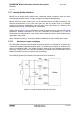
The figure below shows a circuit to connect an external SIM card holder.
Figure 13: External SIM card holder circuit
It is recommended that the total cable length between SMT application interface pads on
BGS12 and the connector of the external SIM card holder must not exceed 100mm in order
to meet the specifications of 3GPP TS 51.010-1 and to satisfy the requirements of EMC com-