
Specifications


CINTERION
®
BGS12 Hardware Interface Description
Contents
40 of 109
Page
BGS12 HID_V00.915
Confidential / Released
2019
-
01
-
07
the module is able to receive data again. This delay depends on the current module
activities (e.g. paging cycle) and may be up to 60ms. The ability to receive data is signalized
by CTS0 and CTS2. It is therefore recommended to enable RTS/CTS flow control, not only in
CYCLIC SLEEP mode, but also in NON-CYCLIC SLEEP mode.
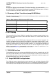
3.5 Summary of State Transitions (except SLEEP Mode)
The table shows how to proceed from one mode to another (grey column = present mode, white
columns = intended modes)
Table 10: State transitions of BGS12 (except SLEEP mode)
Further mode
Power Down Normal mode
Present mode
Power Down mode ---
ON >2
s at VDDLP
level
Normal mode AT^SMSO ---
Normal mode EMERG_RST > 1ms
EMERG_RST > 1ms
And ON has always been at VDDLP level
3.6 RTC Backup
The internal Real Time Clock of BGS12 is supplied from a separate voltage regulator in the
power supply component which is also active when BGS12 is in Power Down mode and
BATT+ is available.
In addition, you can use the VDDLP pad to backup the RTC from an external capacitor. The
capacitor is charged from the internal LDO of BGS12. If the voltage supply at BATT+ is dis-
connected the RTC can be powered by the capacitor. The size of the capacitor determines the
duration of buffering when no voltage is applied to BGS12, i.e. the greater the capacitor the
longer BGS12 will save the date and time. The RTC can also be supplied from an external
battery (rechargeable or non-chargeable). In this case the electrical specification of the
VDDLP pad (see Section 5.4) has to be taken in to account.
3.7 SIM/USIM Interface
The baseband processor has an integrated SIM/USIM card interface compatible with the ISO/
IEC 7816 IC Card standard. This is wired to the host interface in order to be connected to an
external SIM card holder. Five pads are reserved for the SIM interface. BGS12 supports and
automatically detects 3.0V as well as 1.8V SIM cards.
3.7.1 Single SIM/USIM Card Application
The CCIN pad serves to detect whether a tray is present in the card holder. Using the CCIN
pad is mandatory for compliance with the 3GPP TS 11.11 (Rel.99) recommendation if the me-
chanical design of the host application allows the user to remove the SIM card during operation.